5-- 1
© 2012 Mobile Climate Control
T-299 Rev. 08/2012
SECTION 5
ELECTRICAL SCHEMATIC DIAGRAMS
5.1 INTRODUCTION
This section contains Electrical Schematics covering the GEN 4 and GEN 5 systems. Figure 5-3 shows a GEN 4
EM--1 Evaporator with a CM--2/3 Condenser, Figure 5-4 shows a GEN 4 Series EM--1 Evaporator with a CM--2/3 Con-
denser tied into an OEM compressor , Figure 5-5 shows a GEN 4 EM--3 evaporator with (2) CM--3 condensers,
Figure 5-6 shows a (typical) GEN V evaporator with variable speed controls, Figure 5-7 shows a (typical) GEN 5 sys-
tem with Total Control, Figure 5-8 shows a GEN 4 EM--3 with Total Control, and Figure 5-9 shows a (typical) GEN 4
evaporator (s) with Total Control. Contact your Mobile Climate Control Field Service representative or call Mobile Cli-
mate Controls technical hot line at 800--450--2211 for a copy of the schematic for your specific model and/or series.
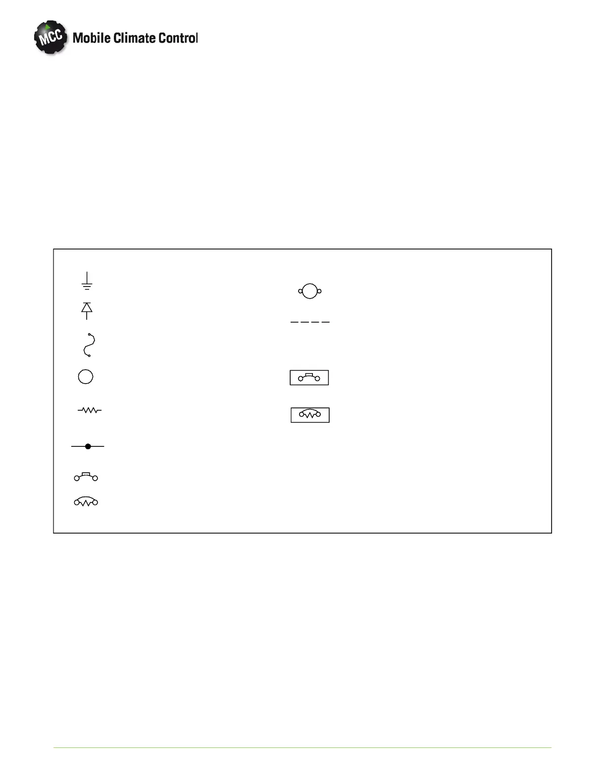
Indicates Wire Ground
Indicates Motor
Indicates Resistor
Indicates Manual Reset Breaker
Indicates Relay Coil
TYPE III MANUAL RESET--RESETS WHEN
EXTERNAL BUTTON IS PUSHED.
CIRCUIT BREAKER IDENTIFICATION
CIRCUIT BREAKER COLOR CODE
Indicates Diode
Indicates Fuse
Indicates Wire Connection
Indicates Reset Breaker
Indicates Optional Wiring
20AMP--------YellowDot
30AMP--------GreenDot
40AMP--------RedDot
Ω Ohm
TYPE II RESETS WHEN POWER
IS REMOVED AND REAPPLIED
Figure 5-1 Electrical Schematic Diagram - Symbols
 Loading...
