CONNECTING TO A RECEIVER USING
TAPE MONITOR JACKS
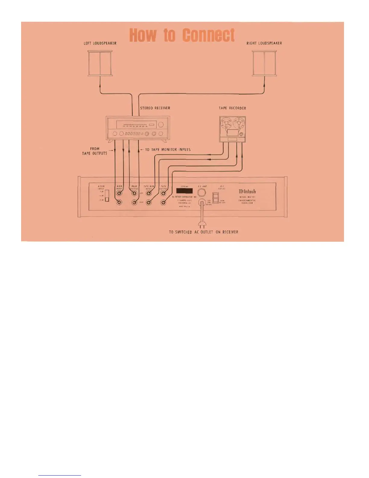
Connect shielded cables between the tape outputs
on the receiver and the MAIN inputs on the MQ101.
Connect shielded cables from the MAIN outputs of
the MQ101 to the tape monitor inputs on the re-
ceiver. The tape recorder can be connected to the
tape monitor facilities on the MQ 101 in conventional
fashion. The length of a connecting cable is limited
by its electrical capacitance. The total capacity of
each cable must not be more than 1000 pF. For in-
stance: Cables with 25 pF per foot may be 40 feet
long. The input impedance of the power amplifier
should be 47,000 ohms or more.
The input attenuation switch on the back panel of
the MQ101 should be in the —12 dB position to pre-
vent the phono cartridge output from overloading the
MQ101 at low frequencies.
PLEASE NOTE —TO USE THE MQ 101 THE TAPE
MONITOR SWITCH ON THE RECEIVER MUST BE
LEFT IN THE "IN" POSITION.
CONNECTING TO A RECEIVER WITH "PREAMP
OUT/POWER AMP IN" FACILITIES
Connect shielded cables between the preamplifier
output jacks and the MAIN inputs on the MQ 101.
Connect shielded cables between the MAIN outputs
on the MQ 101 and the power amplifier inputs on the
receiver. When connected in this fashion make cer-
tain the input attenuation switch on the back panel of
the MQ 101 is in the 0 dB position.
AC POWER OUTLET
The auxiliary AC power outlet can be used to sup-
ply power to other equipment in the system. The out-
let is not switched nor is it fused in the MQ 101.
AC POWER
The MQ 101 operates on 117 to 130 volts, 50/60
Hz. It will be turned on and off when its power cord is
plugged in one of the switched auxiliary AC power
outlets in the program source.
FUSE
The MQ 101 uses a 0.5 Amp fuse. The auxiliary AC
power outlet is not fused.
4
 Loading...