EasyManua.ls Logo

McQuay SEASONCON ALP-037A User Manual

McQuay SEASONCON ALP-037A
43 pages
To Next Page IconTo Next Page
Page #1 background imageLoading...
Page #1 background image
SEASONCON”
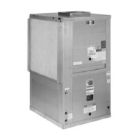
PACKAGED AIR COOLED CONDENSING UNIT
MODELS ALP-037A THRU
057A
&
067B THRU 159B
GROUP
mcQua+PEarEx
Inc. 13600 Industrial Park Blvd., P.O. Box 1551, Minneapolis, Mn. 55440
c$

Questions and Answers:

McQuay SEASONCON ALP-037A Specifications

General IconGeneral
CategoryHeat Pump
ModelSEASONCON ALP-037A
Cooling Capacity3.7 kW
Heating Capacity4.0 kW
RefrigerantR410A
Power Supply220-240V, 50Hz

Summary

Introduction to the McQuay Seasoncon Unit

General Description of the Unit

Overview of the Seasoncon air-cooled condensing unit's design and capabilities.

Unit Nomenclature Explained

Explanation of the model naming convention and component identification.

Inspection Upon Receiving the Unit

Procedures for checking the unit for damage and verifying shipment completeness.

Unit Installation Guidelines

Proper Unit Handling and Lifting

Instructions for safely moving and positioning the condensing unit.

Selecting the Unit Location

Recommendations for optimal placement considering airflow and winds.

Ensuring Service Access

Requirements for accessibility to unit components for maintenance.

Required Unit Clearances

Minimum space requirements around the unit for proper operation and service.

Vibration Isolator Information

Vibration Isolator Selection and Load Data

Guidance on selecting and applying vibration isolators based on unit size and loads.

Refrigerant Piping Requirements

General Refrigerant Piping Guidelines

Basic principles for connecting refrigerant lines to the unit.

Evaporator Above/Below Condensing Unit Piping

Specific piping considerations for different evaporator installation configurations.

Liquid Line Components

Details on available liquid line accessory kits and their components.

Unit Dimensional Drawings

Unit Dimensions and Connection Sizes

Detailed physical dimensions and refrigerant/electrical connection sizes.

Field Wiring and Components

Hot Gas Bypass Kit Components

Description of the optional hot gas bypass accessory kit.

Refrigerant Charge and Pumpdown Capacity

Information on the R-22 refrigerant charge and pumpdown capacity.

Typical Field Wiring Diagrams

Schematics illustrating field wiring for thermostats and controls.

Unit Layout and Principles of Operation

Major Component Locations by Unit Size

Illustrations showing component placement and compressor/fan horsepower.

Control Center Layout and Components

Description and diagrams of the weatherproof control center compartments.

Sequence of Operation for Cooling

Step-by-step explanation of how the unit operates to provide cooling.

Pumpdown Cycle Explanation

How the unit manages refrigerant during shutdown.

Electrical Schematics and Legends

Electrical Legend for Schematic Symbols

Definitions of symbols used in electrical diagrams.

Power Schematics for Motors

Wiring diagrams for compressor and condenser fan motors.

Compressor Control Schematics

Detailed wiring diagrams for compressor control circuits.

Thermostat Circuit Schematics

Wiring diagrams illustrating thermostat connections and logic.

Start-Up and Shutdown Procedures

Pre Start-Up Inspection Checklist

Essential checks to perform before the initial unit start-up.

Initial Unit Start-Up Sequence

Step-by-step instructions for starting the unit for the first time.

Temporary and Extended Shutdown

Procedures for safely shutting down the unit for short or long periods.

System Maintenance Procedures

General Maintenance and Checks

Routine service tasks and checks for optimal unit performance.

Compressor Oil Level Monitoring

How to check and maintain the compressor oil level.

Refrigerant Sightglass Inspection

Checking the sightglass for refrigerant charge status.

Service Actions and Component Replacement

Filter-Drier Core Replacement

Procedure for pumping down and replacing filter-drier cores.

Liquid Line Solenoid Valve Service

Maintenance and replacement of liquid line solenoid valves.

Thermostatic Expansion Valve Service

Adjusting superheat and servicing the expansion valve.

Warranty and Appendix Information

In-Warranty Return Material Procedure

Guidelines for returning parts under warranty for inspection.

Standard Controls - Oil Pressure Safety Control

Description and testing procedure for the oil pressure safety control.

Control System Descriptions

High Pressure Control Operation

How the high-pressure safety switch functions.

Low Pressure Control Operation

How the low-pressure switch operates for unit control.

FANTROL Head Pressure Control

System for automatic condenser fan control based on pressure.

Optional Control Systems

SPEEDTROL Head Pressure Control

Variable speed fan control for head pressure management.

DAMPERTROL Head Pressure Control

Damper system for reducing condenser capacity.

Optional Part Winding Start

Method to reduce compressor start-up current.

Specialized Optional Controls

Low Ambient Start (Optional)

Enables unit operation at low ambient temperatures.

Compressor Lockout (Optional)

Prevents rapid compressor cycling during erratic cooling demands.

Hot Gas Bypass System

Hot Gas Bypass Operation and Adjustment

System for maintaining minimum evaporator pressure and oil return.

Troubleshooting Common Issues

Troubleshooting Chart for Common Problems

Guide to identifying causes and corrective steps for unit malfunctions.

Related product manuals