I
I
I
I
MDR-2000
V3
User's Reference Manual
Data Collection
Field
Name
Starting
Position
Record Type
Record Number
2
Customer Number
5
ID Type
7
Originating
ID
8
ID Type
15
Terminating ID
16
Date
23
Time
27
Duration
31
Flag Byte 37
Meter Pulse
38
Digits
43
Length
Type
Comments
(Bytes)
1 A
XorB
3 9 Modulo 1000
2
9 Usually 00
1
A T, D, A or I
7
9
1
A T, D or A
7 9
4
D mmdd
4
9
hhmm
6 T
hhmmss
1
9
(0 - 7)
5
9
9 See Notes Below
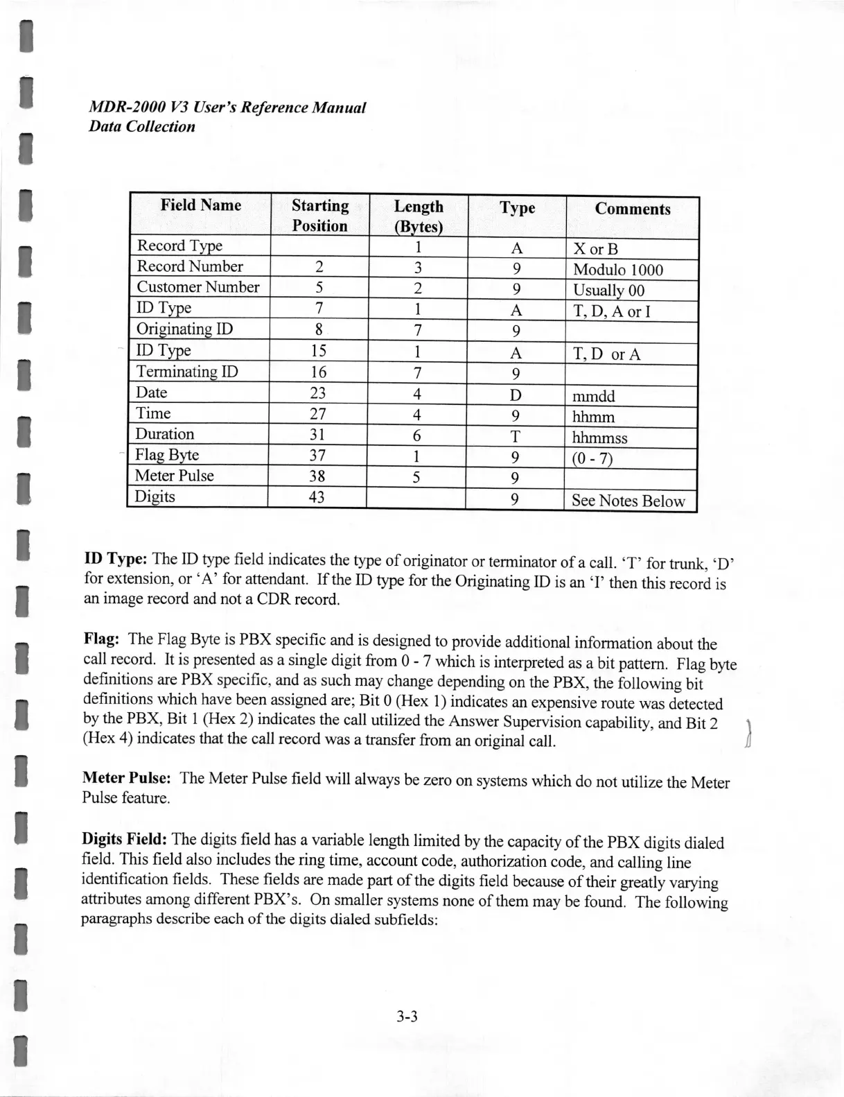
ID
Type: The ID type field indicates the type
of
originator or terminator
of
a call.
'
T'
for trunk, 'D'
for extension, or
'A
' for attendant.
If
the ID type for the Originating ID is an
'I'
then this record
is
an image record and not a CDR record.
Flag: The Flag Byte is PBX specific and is designed to provide additional information about the
call record.
It
is presented as a single digit from 0 - 7 which
is
interpreted as a bit pattern. Flag byte
definitions are PBX specific, and as such may change depending on the PBX, the following bit
definitions which have been assigned are; Bit 0 (Hex
1)
indicates an expensive route was detected
by the PBX, Bit 1 (Hex 2) indicates the call utilized the Answer Supervision capability, and Bit 2
(Hex 4) indicates that the call record was a transfer from an original call.
I
Meter
Pulse: The Meter Pulse field will always be zero on systems which do not utilize the Meter
Pulse feature.
I
I
I
Digits Field: The digits field has a variable length limited by the capacity
of
the PBX digits dialed
field. This field also includes the ring time, account code, authorization code, and calling line
identification fields. These fields are made part
of
the digits field because
of
their greatly varying
attributes among different PBX'
s.
On smaller systems none
of
them may be found. The following
paragraphs describe each
of
the digits dialed subfields:
3-3
 Loading...