EasyManua.ls Logo

Meade LX200 CLASSIC - User Manual

Meade LX200 CLASSIC
11 pages
Print Icon
To Next Page IconTo Next Page
Loading...
Telescope Service
Meade LX200 “Classic” Telescopes
Procedures for Removal and Installation of Printed Circuit Board
And Motor Assemblies
STATIC ELECTRICITY HAZARD AND PREVENTION
Static electricity can easily damage the electronics of your telescope. Great care should
be observed in the handling of the electronics to prevent damage. Note that it is very
easy to generate several thousand volts of static electricity on plastic surfaces just by
handling them. This includes plastic bags, bubble wrap, styrafoam packing materials, as
well as indoor carpet. Take the following precautions:
Work on metal or wooden surfaces.
DO NOT work in an area with a rug on the floor.
Be sure to discharge yourself by touching the metal of the telescope BEFORE
handling the electronics.
DO NOT put the printed circuit board in a plastic bag unless you have the type
designed for holding electronics (conductive plastic bags).
DO wrap the printed circuit board in aluminum foil before packing it in a box if
you don’t have a conductive plastic bag.
Question and Answer IconNeed help?

Do you have a question about the Meade LX200 CLASSIC and is the answer not in the manual?

Overview

This document outlines the procedures for the removal and installation of the Printed Circuit Board (PCB) and motor assemblies for Meade LX200 "Classic" Telescopes. It emphasizes the critical importance of preventing static electricity damage to the sensitive electronic components during these processes.

Function Description:

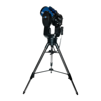
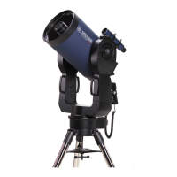
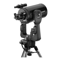
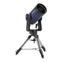
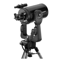
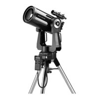
The Meade LX200 "Classic" Telescope is a sophisticated astronomical instrument designed for observing celestial objects. Its functionality relies heavily on the proper operation of its electronic components, particularly the Printed Circuit Board (PCB) and the Right Ascension (R.A.) and Declination (DEC) motor assemblies. The PCB serves as the central control unit, managing the telescope's various functions, including motor control for tracking and pointing, and communication with other components. The R.A. and DEC motors are responsible for the precise movement of the telescope along its two axes, allowing it to track celestial objects as they move across the sky and to point accurately to specific targets. The R.A. motor controls movement in the right ascension axis, which corresponds to the east-west direction, while the DEC motor controls movement in the declination axis, corresponding to the north-south direction. Together, these components enable the telescope to perform its primary function of astronomical observation with accuracy and stability.

Usage Features:

The document primarily focuses on maintenance procedures rather than direct usage features. However, understanding these maintenance steps is crucial for ensuring the continued optimal performance of the telescope's usage features. The proper functioning of the PCB and motor assemblies directly impacts the telescope's ability to:

  • Accurate Tracking and Pointing: The R.A. and DEC motors, controlled by the PCB, are essential for the telescope's ability to accurately track celestial objects and point to specific coordinates. Any issues with these components would compromise the telescope's primary function.
  • Stable Operation: The document mentions the importance of proper meshing between the worm gear and worm wheel, and the role of springs in the motor assemblies to compensate for imperfections. This ensures smooth and stable movement, which is critical for clear observations and astrophotography.
  • User Control: While not explicitly detailed, the PCB facilitates the interface between the user's commands (e.g., through a hand controller or computer) and the physical movements of the telescope.

Maintenance Features:

The document provides detailed, step-by-step instructions for the removal and installation of the PCB and motor assemblies, highlighting several key maintenance features and considerations:

  • Static Electricity Prevention: This is the most emphasized maintenance aspect. The document provides a dedicated section on "STATIC ELECTRICITY HAZARD AND PREVENTION," outlining crucial precautions:
    • Working on metal or wooden surfaces.
    • Avoiding work on rugs or carpets.
    • Discharging oneself by touching the telescope's metal before handling electronics.
    • Using conductive plastic bags or aluminum foil for storing PCBs. This highlights the extreme sensitivity of the telescope's electronics to electrostatic discharge, which can cause irreversible damage.
  • Tools Required: A specific list of tools is provided, including Phillips head screwdrivers, hex wrenches (Allen heads), a putty knife, and solvent (alcohol). This ensures that users have the necessary equipment for the procedures.
  • PCB Removal and Installation:
    • Careful Disassembly: Instructions detail how to disconnect power, remove the telescope from its mount, and carefully lay it on a work surface. The importance of unlocking R.A. and DEC knobs is noted to prevent damage to motor assemblies.
    • Cover Removal: Specific steps for removing the drive base cover, including identifying and removing various types of screws (Phillips head, hex screws), are provided.
    • Cable Disconnection: Clear instructions for disconnecting the 7-conductor motor cable and the 34-conductor ribbon cable from the PCB connector are given, with a warning against pulling too hard to avoid loosening wires.
    • Resistor Assembly Handling: If applicable, instructions for removing the resistor mount clip and leaving resistors attached are included.
    • Mounting Screw Management: The document advises marking mounting holes for reinstallation and noting the number of screws used, as it can vary.
    • PCB Installation Checks: During installation, it's crucial to check for nylon standoff washers on the back of the circuit board to prevent short circuits.
    • Resistor Assembly Mounting (Thermal Management): Detailed steps for cleaning the mounting surface, placing resistors in the clip, applying thermal joint compound (thermal grease) to ceramic resistors, and securing the clip with double-sided tape or silicone adhesive are provided. This ensures proper heat dissipation for the resistors.
    • Cable Reconnection: Specific instructions for installing the 34-conductor Front Panel Ribbon cable, with a strong warning to "DOUBLE CHECK" for correct placement to prevent PCB damage, and installing the 7-pin R.A. motor connector.
    • Heat Sink Application: Spreading a thin coat of thermal joint compound over the aluminum heat sink is specified, indicating its role in dissipating heat from critical components.
  • R.A. Motor Removal and Installation:
    • Cable Disconnection: Disconnecting the 7-pin R.A. motor cable from the PCB is the first step.
    • Screw Management: A warning is given to be very careful not to drop hex screws into the base, as retrieval is difficult and could jam the worm gear.
    • Spring Management: The presence of a spring between the motor assembly sides, ensuring proper meshing of the worm with the worm wheel, is highlighted. Users are instructed to keep pressure on the motor assembly hinge to prevent the spring from falling out.
    • Installation Alignment: Aligning the motor assembly with mounting holes, applying grease to the base and mounting plate, compressing the spring-loaded hinge, and aligning the worm wheel teeth with the worm gear are critical steps.
    • Screw Tightening Sequence: A specific sequence for loosely threading, semi-tightening, and firmly tightening the mounting screws is provided, along with instructions to push up on the motor base to level the assembly.
    • Tension Screw Adjustment: The tension screw needs to be adjusted to allow for 1/16” of movement, compensating for high and low spots in the worm gear drive and preventing disengagement or binding.
  • DEC Motor Removal and Installation:
    • Knob and Cover Removal: Instructions for removing the declination lock knob and plastic cover are given.
    • Pre-Removal Observation: It's suggested to observe how the motor assembly aligns with the fork arm mounting holes before removal, and to gently rock the optical tube assembly to see how the motor assembly flexes. This helps in understanding the reassembly process.
    • Motor Cable Disconnection: Unplugging the motor power cable from the inside fork arm connector is specified.
    • Slow Motion Knob Removal: If applicable, removing the declination slow motion knob is required.
    • Spring Management: Similar to the R.A. motor, the presence of a spring ensuring proper meshing is noted, and users are advised to keep pressure on the hinge during removal.
    • Cable Routing: During installation, the power cable must be passed through an opening in the fork arm and plugged into the RJ-45 jack.
    • Mounting Plate and Grease: The use of a special mounting plate for some motor assemblies is mentioned, and applying grease to hold components together during installation is recommended.
    • Alignment and Meshing: Emphasizes keeping pressure on the spring, carefully aligning the worm wheel teeth with the worm gear, and centering mounting holes.
    • Tube Assembly Adjustment: Adjusting the tube assembly to shift the motor assembly left is necessary for the worm wheel to clear the reduction gear box and for proper meshing.
    • Screw Tightening and Tension: Similar to the R.A. motor, a specific tightening sequence and tension screw adjustment (1/16” movement) are required to ensure smooth operation and prevent binding.
    • Gear Action Check: After installation, checking the gear action by turning the declination slow motion knob and applying lithium grease if not smooth enough is recommended.

Overall, the document serves as a comprehensive guide for maintaining the electronic and motor components of the Meade LX200 "Classic" Telescope, with a strong emphasis on careful handling and precise assembly to ensure the longevity and performance of the instrument.

Meade LX200 CLASSIC Specifications

General IconGeneral
Optical DesignSchmidt-Cassegrain
Focal Length2000 mm
Focal Ratiof/10
GoTo SystemYes
MotorizedYes
Finderscope8x50
Aperture8 inches (203.2 mm)
Mount TypeFork
Hand ControllerYes
Database64, 000+ objects
Weight60 lbs (27.2 kg)
EyepieceSuper Plössl 26mm
Tracking ModesAltazimuth, Equatorial

Related product manuals