7
Universal Energy Meter MEg40
+
3/ FUNCTION DESCRIPTION
Compared with the original universal monitor MEg40, the universal energy meter
MEg40
+
oers extended functions to measure electrical energy. When measuring energies,
it stores measured values into non-destructive registers and allows also additional creation
of tari bands and load proles, without limitation of their number and time. anks
to the possibility of subsequent analysis, MEg40
+
can be used in locations with a set of
functionally independent consumptions unspecied in advance, e.g. in manufacturing
and commercial complexes.
e instrument MEg40
+
has a set of six energy registers for each phase according to
standard IEC 62053-23, see Fig. 1. ey are the following registers:
OBIS: 1.1.1.8.0 E
P+
- active energy, consumption
OBIS: 1.1.2.8.0 E
P-
- active energy, delivery
OBIS: 1.1.5.8.0 E
QL/P+
- reactive energy inductive at consumption
OBIS: 1.1.7.8.0 E
QL/P-
- reactive energy inductive at delivery
OBIS: 1.1.8.8.0 E
QC/P+
- reactive energy capacitive at consumption
OBIS: 1.1.6.8.0 E
QC/P-
- reactive energy capacitive at delivery
e set of six registers for an outlet is located in the basic non-destructive memory of the
instrument and the set of six distributed registers of the individual phases is located in the
data ash memory that can be realized as a memory card.
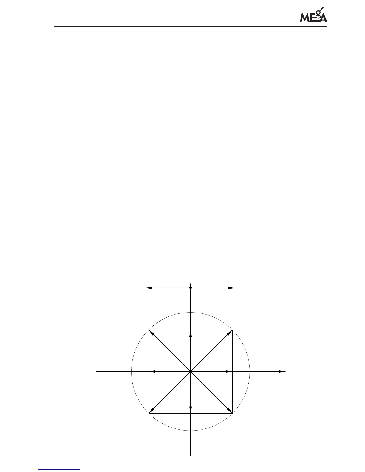
Fig. 1: Denition of quadrants of active and reactive energy according to IEC 62053-23
half-plane delivery half-plane consumption
Quadrant II Quadrant I
Quadrant III Quadrant IV
Q+
P-
P+
Q-
U
E
S
QC/P-
EQL/P+
E QL/P- E QC/P+
E P- E P+
 Loading...