Do you have a question about the MegaSquirt MS3 and is the answer not in the manual?
Legal and emissions compliance information for the hardware.
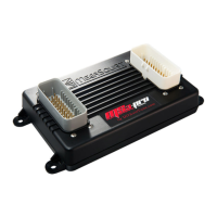
Essential tools needed for Megasquirt installation and configuration.
Guidance on navigating the manual to understand concepts and wiring for EFI components.
Clarification on the manual's focus on the MS3/V3.0 mainboard, excluding MS3X functionalities.
General description of the Megasquirt ECU, its function, and component interactions.
Recommendations for installing the Megasquirt unit, considering temperature and environmental protection.
Details on wiring harnesses, crank/cam inputs, sensor inputs, outputs, and tuning interfaces.
Guidelines for wiring: wire choice, soldering/crimping, fusing, relay standards, and power routing.
Critical guidance on establishing proper grounding points for reliable sensor readings and system operation.
Diagrams detailing main connections, optional circuits, internal I/O, and the relay board for system integration.
Details on various sensor inputs including Crank/Cam, MAP, IAT/MAT, CLT, TPS, O2, MAF, Flex, and spare ADC inputs.
Information on outputs for Fuel Injectors, Ignition, Fuel Pump, Idle Valve, Tacho, Boost Control, and Alternator.
Important safety precautions regarding the high voltages produced by ignition systems.
Crucial setup for tach inputs; correct installation and configuration are vital for RPM reading and system operation.
Obtaining a tach trigger from a single coil's negative terminal for fuel-only installs.
Wiring and setup for VR sensors, including the conditioner circuit and connecting to Megasquirt's tach-in.
Guide to Hall effect sensors, typically three-wire, acting as switches to ground with magnetic fields.
Wiring and configuration for various sensor types including Hall, geartooth, logic, and optical sensors.
Hall sensors with internal pull-up resistors providing 0V or 5V signals, simplifying connection.
Using gear-tooth sensors, a variant of Hall sensors, for crank and cam triggering with magnetic built-in capability.
Specific wiring for GM LS 24X crank and cam sensors, detailing supply voltage and sensor logic.
Specific wiring for GM LS 58X crank and cam sensors, detailing supply voltage and sensor logic.
Guide to optical sensors, acting as switches to ground with light, often requiring a pull-up resistor.
Converting distributor points to a tach input, requiring locking advance and phasing for Megasquirt timing control.
Using ignition modules that combine tach input and coil driving, presenting a digital signal to the Megasquirt.
Connecting Mitsubishi CAS and GM Optispark systems, supporting high-resolution signals for improved ignition accuracy.
Support for specific CAS types like 4G63 and 6G72 using special decoders for their trigger patterns.
Using aftermarket trigger discs with Mitsubishi CAS for standard patterns, requiring 'Toothed Wheel' mode.
Internal modifications to add a cam sensor input for engines requiring dual tach inputs like coil-on-plug ignition.
Steps for building internal circuits to drive ignition coils, requiring interface circuits for all outputs.
Building a single high-current ignition output for directly driving an inductive coil using BIP373.
Circuit for driving logic coils using FET drivers, requiring 'Going High' spark output setting.
Simple method for wiring logic outputs using resistors, requiring 'Going Low' spark output setting.
Adding an optional DB15 connector for additional spark outputs when main connector pins are insufficient.
Directly connecting logic coils that accept 0-5V signals from Megasquirt, containing internal ignition drivers.
Wiring and configuration for LS1 coils, advising a 3.5ms dwell and 'Going High' spark output setting.
Wiring and configuration for LS2 coils, advising a 3.5ms dwell and 'Going High' spark output setting.
Pin-out and wiring details for D585 truck coils, requiring a 3.5ms dwell and 'Going High' spark output setting.
Diagram showing the general layout for connecting 4-cylinder coil-on-plug systems using LS coils.
Wiring and pin-out for the IGN1A logic coil, a high-energy aftermarket coil requiring 'Going High' spark output.
Pin-out and wiring for a single logic coil used with distributors, requiring 'Going High' spark output.
Wiring for a 4-tower wasted spark logic coil, common in VAG vehicles, requiring 'Going High' spark output.
Pin-out and wiring for a 4-way logic coil from VW/Jetta/Skoda, requiring 'Going High' spark output.
Wiring for 4-wire logic COPs, specifying dwell times and requiring 'Going High' spark output.
Using ignition amplifier modules to drive high-current coils, keeping ignition noise outside the Megasquirt.
Information on high-current coils requiring ignitors or custom drivers.
Connecting CDI modules using a 'white wire' trigger input for ignition control.
Ignition support modes for Mazda rotary engines (FC, FD, RX8).
Wiring Toyota DLI systems using multiplexed signaling, requiring specific software settings.
Using a coil negative trigger for fuel-only installs, not suitable for wasted spark or CDI coils.
Traditional distributor methods for spark timing, including mechanical/vacuum advance and breakerless systems.
Configuring distributor input phasing, locking advance mechanisms, and the recommendation for crank trigger wheels.
Critical step of rotor phasing to prevent cross-firing and ensure proper engine operation.
Using trigger return mode for accurate timing with both edges of a vane/slot.
Using a flying magnet crank trigger for improved ignition control, eliminating distributor slop.
Preferred method using a trigger wheel on the crank for accurate ignition control.
Details on Ford TFI modules, focusing on PIP and SPOUT connections for ignition control.
Wiring and configuration for GM HEI7 distributors designed for computer timing control.
Similar to HEI7 but with different packaging; requires same internal modifications for ignition control.
Using aftermarket dual-sync distributors for clean trigger signals.
Overview of the Ford EDIS system, its components, and ECU wiring.
Critical phasing relationship between VR sensor and missing tooth for EDIS module operation.
Procedure for confirming ignition timing with EDIS, including limp home mode and fixed timing checks.
Comparison of GM DIS ignition to HEI7, noting ECU does not receive cylinder ID or phase info.
Support for various trigger wheel combinations and their compatibility with Megasquirt spark modes.
Common trigger wheel configurations and their naming conventions.
Common configurations for wasted spark using 36-1 or 60-2 crank wheels.
Using missing tooth cam wheels for sequential triggering, noting accuracy limitations.
Common arrangement supporting full sequential and COP, using missing tooth crank and single tooth cam.
Arrangement using missing tooth crank and polled cam wheels for full sequential triggering.
Connecting Nippondenso CAS for sequential and COP/wasted spark.
Using aftermarket discs with Mitsubishi CAS for single coil/wasted spark.
Wiring Mitsubishi CAS with aftermarket discs for coil-on-plug, requiring cam input.
General principles for applying trigger wheel configurations not explicitly covered.
Wiring and configuration for Ford Zetec engines using 36-1 crank wheel.
Crank and cam signal patterns for Chrysler Neon/420A engines.
Chrysler's 'next gen crank' pattern for consolidating crank/cam patterns.
Mode for Subaru and Mazda RX8 engines with stock trigger wheels.
Miata 99-05 ignition setup using low-resolution crank and camshaft teeth.
Mode for Subaru EJ series engines with unique 6/7 trigger.
Applications for Mitsubishi 6G72 engines, using optical CAS.
Application for Ford Sierra Cosworth and Fiat/Lancia engines.
Connecting Mitsubishi CAS 4/1 with optical distributors.
Wiring for Mitsubishi 4G63 engines with distributorless ignition.
Using Mitsubishi optical CAS on 2G 4G63 and pre-1999 Miata.
Mode for 4-cylinder bike engines with single tooth and two pickup coils.
Unique setup for Chrysler 2.2/2.5 engines using 4-tooth cam trigger.
Trigger mode for Renault/Jeep engines requiring cam sensor.
Suzuki Swift engines with distributors, VR sensors, and irregularly spaced teeth.
Vitara 2.0 variant using an uneven crank wheel with eleven teeth.
Experimental mode for Daihatsu 3-cylinder engines with distributor trigger.
Experimental mode for Daihatsu 4-cylinder engines with distributor trigger.
Honda V-twin motorcycles using 12-3 crank trigger with VR sensor.
Rover K-series engines with 36-tooth crank trigger and two 1-tooth gaps.
Rover K-series engines with 36-tooth crank trigger and four 1-tooth gaps.
Rover K-series engines with differently positioned gaps.
GM 7X trigger wheel system with six equally spaced teeth and a seventh for cylinder ID.
Nissan QR25DE engines requiring crank and cam sensors.
Honda RC51/RC46/FSC600/CBR variants using 12-tooth crank and 3-tooth cam triggers.
Chevrolet LS1 V8s using a 24X crank pattern.
Chevrolet LS2 V8s using a 58X crank pattern.
Yamaha YZF1000/FZR models using 60-tooth crank and 2-missing teeth.
Harley Davidson with 32-2 crank trigger, using VR sensor and MAP.
Miata 99-05 with aftermarket 36-2 crank trigger, requiring VR sensors.
Fiat 1.8 16V engines using irregular 6-tooth crank and 3-tooth cam triggers.
GM Optispark system using optical triggers, supporting sequential fuel and single coil.
Add-on boards for increased inputs/outputs and CAN communications.
Typical wiring for a wet nitrous system using specific Megasquirt pins.
Guide to locating EDIS4 modules and VR sensors in Ford Escort/Mercury Tracer.
Identifying EDIS4 modules in European Ford vehicles.
Locating EDIS6 modules in European Ford Mondeo V6 and Scorpio.
Sourcing 36-1 trigger discs from Ford Sierra or aftermarket suppliers.
Introduction to DIY soldering, required tools, and component handling for the V3.0 mainboard.
Key build choices like spark drivers, PWM idle support, and cam input circuits.
Step-by-step guide to assembling the Megasquirt V3.0 board, assuming basic soldering skills.
List of parts used to assemble the V3.0 main board, with quantities, references, and descriptions.
| Clock Speed | 40 MHz |
|---|---|
| Real Time Clock | Yes |
| Knock Control Channels | 2 |
| Lambda/Wideband Input | Yes |
| EEPROM | 4 KB |
| Fuel Control | Sequential, semi-sequential, batch |
| Ignition Control | Distributor, wasted spark, coil-on-plug |
| Communication | CAN, USB, RS232 |
| Tuning Software | TunerStudio MS |
| Number of Injector Outputs | 8 |
| Number of Ignition Outputs | 8 |
| Number of Digital Inputs | 16 |
| Number of Analog Inputs | 8 |
| Data Logging | Internal SD card |
| Operating Temperature | -40°C to 85°C |