27
3.2.5 Programming
This section through the "man-machine interface +PLC+MTC" this application system to explain the
general use of MTC thermostat. Taking MEGMEET series PLC as an example, ModBus is used for
communication between man-machine interface and PLC, and McBus is used for communication
between PLC and MTC. PLC station number is 0 and MTC station number is 1. 1. Set the parameters of
MTC. See chapter 4 for the MTC wizard Settings.
2. With the D and M components open to the user, PLC and man-machine interface can be used to
monitor and measure MTC. Let's expand on that.
Note: the D elements listed in table 3-2 and the dedicated M elements in the attachment are the
dedicated soft elements of the thermostat. Users are not allowed to use them for other purposes.
MTC provide some dedicated D and M components. For dedicated M components, users can operate
directly (see appendix I list of MCbus dedicated M components). For the D element, the user can operate
through the five command words described above.
Read command 4
1. The main module defines the frame with the MCbus communication buffer. D component definitions
are shown in the following table
Table 3-3 Settings represent communication special meaning D element
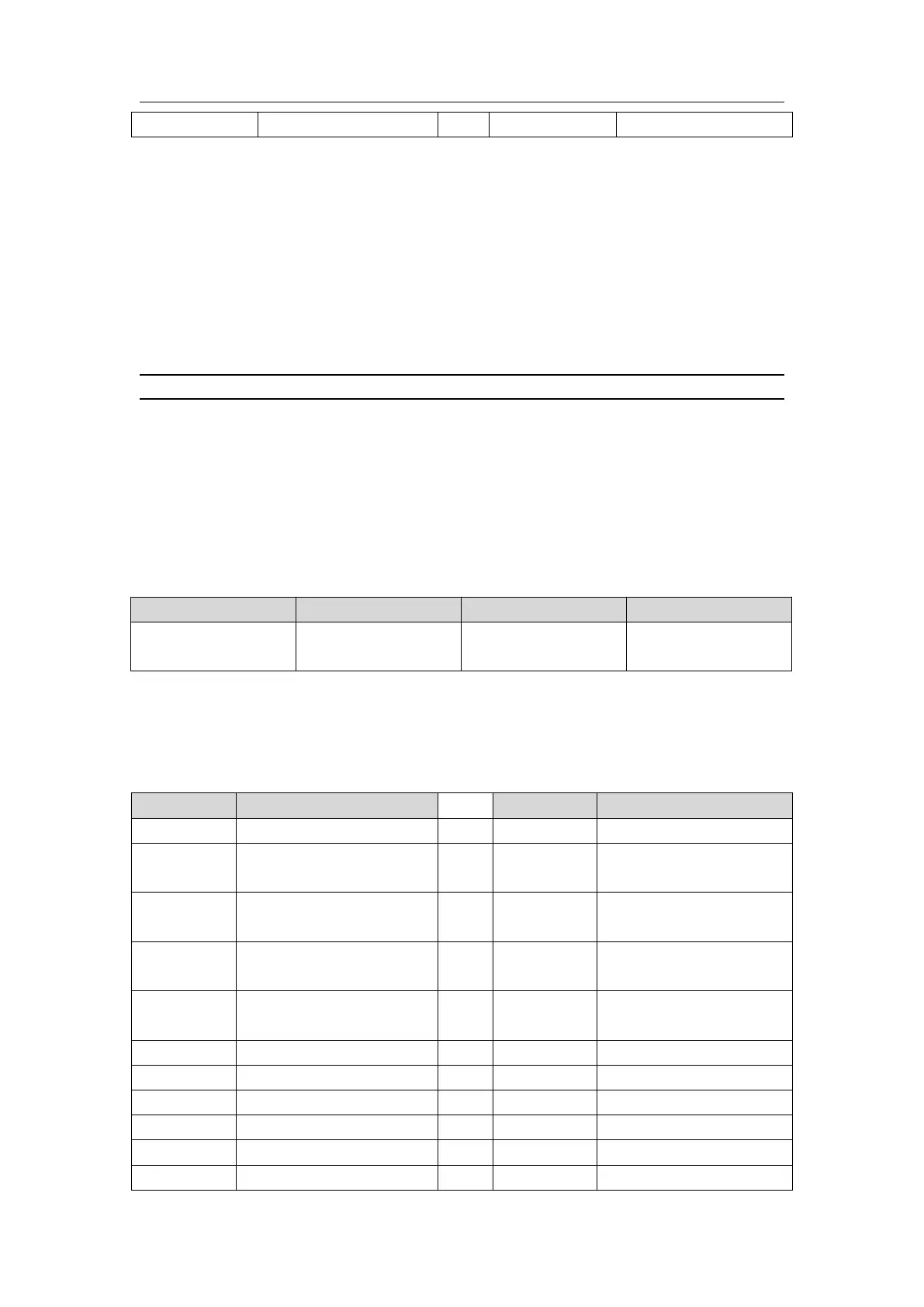
2. MTC thermostat return the frame with the MCbus communication buffer. Take MTC#1 region as an
example: when D7532 and D7563 become 4, data can be read from MTC, up to 30 D elements can be
read at a time, as shown in the following table.
Table 3-4 D component definitions 1
CH1 multi-step current
execution segment
CH2 multi-step current
execution segment
CH3 multi-step current
execution segment
CH4 multi-step current
execution segment
CH1 heat control output value
Cool control output status
CH2 heat control output value
MTC module station
number to be read
 Loading...