Installation Rev 1.6
Mellanox Technologies
15
4. Mount the system into a rack enclosure - see “19” Systems Mounting Options” on page 17.
5. Power on the system - refer to “Initial Power On” on page 40.
6. Perform system bring-up - see “System Bring-Up” on page 42.
7. [Optional]: FRU replacements are described in Section 2.9 on page 47.
2.3 Air Flow
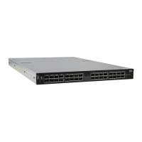
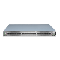
Mellanox systems are offered with two air flow patterns:
• Power (rear) side inlet to connector side outlet - marked with blue power supplies/fans-
FRUs’ handles, as shown in Figure 6.
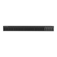
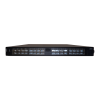
• Connector (front) side inlet to power side outlet - marked with red power supplies/fans
FRUs’ handles, as shown in
Figure 7.
Table 6 provides an air flow color legend and respective OPN designation
The following information does not apply to SN2100. In the SN2100 systems, the fan
units are non-replaceable.
All servers and systems in the same rack should be planned with the same airflow
direction.
All FRU components need to have the same air flow direction. A mismatch in the air
flow will affect the heat dissipation.
Table 6 - Air Flow Color Legend
Direction
OPN
Designation
Description
Ending with
“-R”
Connector side inlet to power side outlet.
Red latches are placed on the power inlet
side.
 Loading...