Installation Rev 1.6
Mellanox Technologies
11
4. Mount the system into a rack enclosure - see “Mounting Options” on page 12.
5. Power on the system - refer to “Initial Power On” on page 29.
6. Perform system bring-up - see “System Bring-Up” on page 30.
7. [Optional]: FRU replacements are described in Section 2.10 on page 34.
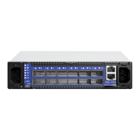
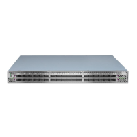
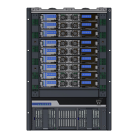
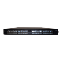
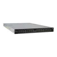
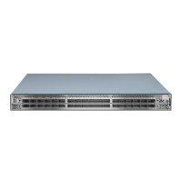
2.3 Air Flow
Mellanox systems are offered with two air flow patterns:
• Power (rear) side inlet to connector side outlet - marked with blue power supplies/fans-
FRUs’ handles, as shown in Figure 4.
• Connector (front) side inlet to power side outlet - marked with red power supplies/fans
FRUs’ handles, as shown in
Figure 5.
Table 6 provides an air flow color legend and respective OPN designation
All servers and systems in the same rack should be planned with the same airflow
direction.
All FRU components need to have the same air flow direction. A mismatch in the air
flow will affect the heat dissipation.
Table 6 - Air Flow Color Legend
Direction
OPN
Designation
Description
Ending with
“-R”
Connector side inlet to power side outlet.
Red latches are placed on the power inlet
side.
Ending with
“-F”
Power side inlet to connector side outlet.
Blue latches are placed on the power inlet
side.
 Loading...