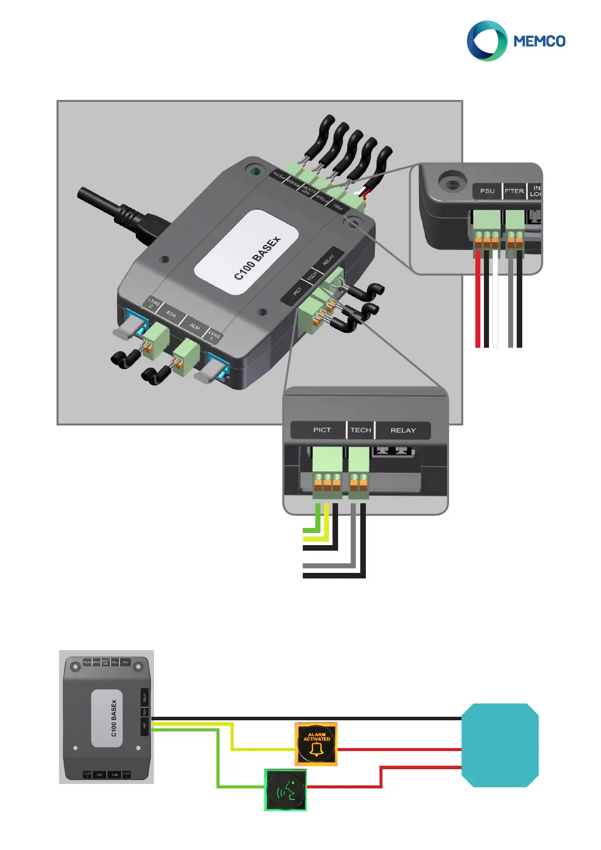
Connections to the Main Unit
Telephone line (PSTN /GSM)
Serial (RS485)
Inductive Loop
Alarm Filtering
10-30VDC PSU
C100 Programming Tool
Relay *
Technical Input
Pictograms (0V)
* [MAX switching voltage of 60VDC or
42.4VAC (peak)/30VAC (rms)]
End of Alarm
LVAS 2
LVAS 1
Alarm Button 0V
(Automatically detects
N/O or N/C)
0V return to pictogram power supply
5-24VDC Signal
Isolated 0V return
Call placed Pictogram
Call answered Pictogram
Power OK input signal (0V = on backup, 12V = on mains
0V
10-30VDC supply
5-24VDC Signal
Isolated 0V return
Please see details below of all connections available on the C100 BASE1 and BASE2 units. All connections that have a
specic polarity; required specic connections within the connector are explained in the zoomed-in sections.
Connecting External Pictograms
As long as external pictograms are powered by an independent power supply, the C100 can control their operation.
These pictograms should be connected as below:
External
PSU
Connections as per pictograms
connections detailed on the above
diagrams
OV
Voltage supply required
Voltage supply required