Do you have a question about the Mercoid PPQ Series and is the answer not in the manual?
The Mercoid Series PPQ Differential Pressure Controls are designed to make or break electrical circuits based on small changes in the differential between two pressures, whether positive or vacuum. These controls are suitable for applications such as indicating changes in resistance across a filter, changes in differential due to airflow conditions, or interruptions in airflow.
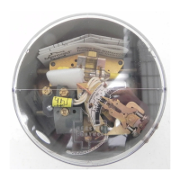
The device operates using two pressure chambers separated by a sensitive diaphragm. Each chamber connects to a separate pressure source, and the control is set to activate when the relationship between these two pressures changes. The operating difference required to activate the switch is adjustable within specified limits, and this range is available throughout the control's overall range. The change in pressure difference needed to restore the switch to its original position (reset value) is fixed and not adjustable, remaining constant once the operating pressure difference is established.
Types PPQ, PPQW, and PPQE (with suffixes -2 or -3) are equipped with single-contact mercury switches, providing single-stage operation for single-pole, single-throw make and break circuits. For controls with suffix -2, the switch contact opens when the pressure difference between chambers increases (high side pressure increases or low side pressure decreases). The circuit closes (resets) when the pressure difference decreases. To adjust, if the mercury contact (Switch 9-81) is open when the pressure difference is below the cut-out (Operating Difference), turn adjustment screw "S" clockwise to close the switch contact. For controls with suffix -3, which incorporate normally closed mercury switch contacts, if the mercury switch (9-83) contact is open when the pressure difference is above the cut-out (Operating Difference), turn adjustment screw "S" counter-clockwise to close the switch contact. To increase (widen) the operating differences required to open the switch contact (cut-out), turn adjustment screw "S" clockwise. To decrease (narrow) the operating difference, turn screw "S" counter-clockwise.
Types PPQ, PPQW, and PPQE with suffixes -4122, -4123, -4129, or -4132 incorporate two SP-ST mercury switches, enabling two-stage operation. This means one contact operates at a different pressure value than the other.
This configuration features two contacts that close successively upon an increase in pressure difference. The HIGH pressure source connects to the REAR pressure connection, and the LOW pressure source connects to the FRONT pressure connection. Operation: Both switch contacts open one after the other as the pressure operating difference increases from low to high differential settings. With both switches closed (low differential pressure), the REAR SWITCH (9-81) opens as the pressure difference increases. The FRONT SWITCH (9-83) opens as the pressure difference increases further. When pressure differences decrease, the FRONT SWITCH closes first, then the REAR switch. The sensitivity (reset value) is not adjustable. Adjustment: Screw "S" changes the operating pressure difference for both contacts. Turning "S" clockwise increases (widens) the pressure difference, opening the switch contacts. Counter-clockwise decreases (narrows) it. This adjustment also sets the low operating differential pressure for the REAR switch. If the rear switch is open, turning "S" clockwise will close it. Screw "D" (small slotted screw on magnet arm) adjusts the spread between the REAR (low differential) and FRONT (high differential) contact operations. Turning "D" clockwise increases (widens) the spread, and counter-clockwise decreases (narrows) it. Changes to "S" may require readjustment of the FRONT switch with "D".
This configuration features two contacts: one opens upon an increase in pressure difference, and the other opens upon a decrease in pressure difference. The HIGH pressure source connects to the REAR pressure connection, and the LOW pressure source connects to the FRONT pressure connection. Operation: With both mercury switch contacts closed (neutral zone), the FRONT contact (9-83) opens as the pressure difference increases. It recloses as the difference decreases. If the pressure difference decreases below the neutral zone, the REAR contact (9-83) opens. It recloses as the difference increases. The sensitivity (reset value) is not adjustable. Adjustment: Screw "S" changes the operating differences for both contacts. Turning "S" clockwise increases (widens) the pressure difference, opening the switch contacts. Counter-clockwise decreases (narrows) it. This adjustment also sets the low operating differential pressure for the REAR switch. If the rear switch is open, turning "S" counter-clockwise will close it. Screw "D" (small slotted screw on magnet arm) adjusts the spread between the REAR (low differential) and FRONT (high differential) contact operations. Turning "D" clockwise increases (widens) the spread, and counter-clockwise decreases (narrows) it. Changes to "S" may require readjustment of the FRONT switch with "D".
This configuration features two contacts that close successively upon an increase in pressure difference. The HIGH pressure source connects to the REAR pressure connection, and the LOW pressure source connects to the FRONT pressure connection. Operation: Both switch contacts close successively as the pressure operating difference increases from low to high differential settings. With both switches open (low differential pressure), the REAR switch (9-83) closes as the pressure difference increases. The FRONT switch (9-81) closes as the pressure difference increases further. With decreasing pressure differences, the FRONT switch opens first, then the REAR switch. The sensitivity (reset value) is not adjustable. Adjustment: Screw "S" changes the operating differences for both contacts. Turning "S" clockwise increases (widens) the pressure difference, closing the switch contacts. Counter-clockwise decreases (narrows) it. This adjustment also sets the low operating differential pressure for the REAR switch. If the rear switch is closed, turning "S" clockwise will open it. Screw "D" (small slotted screw on magnet arm) adjusts the spread between the REAR (low differential) and FRONT (high differential) contact operations. Turning "D" clockwise increases (widens) the spread, and counter-clockwise decreases (narrows) it. Changes to "S" may require readjustment of the FRONT switch with "D".
This configuration features two contacts: one closes upon an increase in pressure difference, and the other closes upon a decrease in pressure difference. The HIGH pressure source connects to the REAR pressure connection, and the LOW pressure source connects to the FRONT pressure connection. Operation: With both mercury switch contacts open (neutral zone), the FRONT contact (9-81) closes as the pressure difference increases. It reopens as the difference decreases. If the pressure difference decreases below the neutral zone, the REAR contact (9-81) closes. It reopens as the difference increases. The sensitivity (reset value) is not adjustable. Adjustment: Screw "S" changes the operating differences for both contacts. Turning "S" clockwise increases (widens) the pressure difference, closing the switch contacts. Counter-clockwise decreases (narrows) it. This adjustment also sets the low operating differential pressure for the REAR switch. If the rear switch is closed, turning "S" counter-clockwise will open it. Screw "D" (located on magnet arm) adjusts the spread between the REAR (low differential) and FRONT (high differential) contact operations. Turning "D" clockwise increases (widen) the spread, and counter-clockwise decreases (narrows) it. Changes to "S" may require readjustment of the FRONT switch with "D".
| Brand | Mercoid |
|---|---|
| Model | PPQ Series |
| Category | Controller |
| Language | English |