DMT 2004 Digital Multimeter 91‑892647A01
NOTE: Due to manufacturing differences, meter internal polarity may vary from manufacturer to manufacturer. As a result, the
test readings may be a direct reversal of the readings specified. If so, reverse the meter leads and perform the test again.
A slight variance from the listed specification does not necessarily indicate a defective component.
Meter Test Leads
Meter Scale Reading
Black Red
White
Red Diode OUCH
Yellow Diode 1.3–2.2 Ω
Ground Diode 0.3–0.9 Ω
Yellow
Red Diode OUCH
White Diode 1.3–2.2 Ω
Ground Diode 0.3–0.9 Ω
Red
Yellow Diode 0.3–0.9 Ω
White Diode 0.3–0.9 Ω
Ground Diode 0.7–1.3 Ω
Ground
White Diode 1.2–1.8 Ω
Yellow Diode 1.1–1.8 Ω
Red Diode OUCH
IMPORTANT: Be certain to secure the wires with the reusable cable tie, prior to placing the engine back into service.
Voltage Regulator/Rectifier Removal and Installation
Removal
1.
Release the reusable cable tie that secures the voltage regulator/rectifier wires.
2. Disconnect the bullet connectors for the white, yellow, and red wires from the voltage regulator/rectifier.
3. Remove the two screws that secure the voltage regulator to the bracket, and remove the voltage regulator.
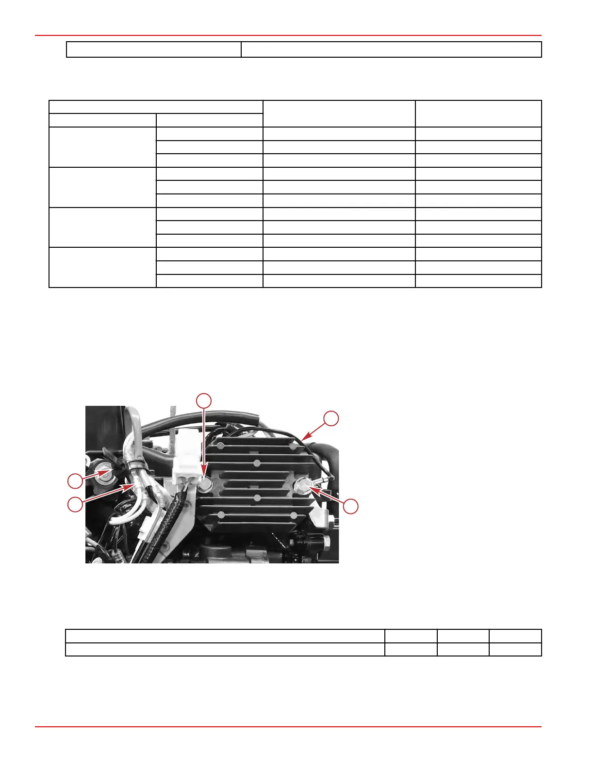
a - Bullet connectors
b - Reusable cable tie
c - Voltage regulator mounting screws (2)
d - Voltage regulator ground (black) wire
Installation
1.
Attach the voltage regulator to its mounting bracket with two screws. Be certain to attach the ring terminal for the ground
(black) wire with one of the screws.
2. Tighten the screws to the specified torque.
Description Nm lb‑in. lb‑ft
Voltage regulator mounting screws 6.0 53.1 –
3. Attach the three bullet connectors for the red, yellow, and white wires, to complete the electrical connections.
4.
Secure the wires at the bullet connectors with the reusable cable tie.
Charging and Starting Systems
Page 2B-10 © 2018 Mercury Marine 90-8M0125265 eng NOVEMBER 2017
 Loading...


