Theory of Operation
Air Induction System
The air induction system consists of an intake manifold with an intake runner to each cylinder for a smooth air flow to the
combustion chamber. Each runner has a single fuel injector controlled by the ECM. The fuel injector has several very small
holes in the fuel injector nozzle tip, to help atomize the fuel when injected into the runner as the cylinder intake valve opens.
A single throttle body/shutter with an attached throttle position sensor (TPS), along with the idle air control (IAC) valve,
manages the amount of air entering the induction system. A combined manifold air temperature (MAT) and manifold absolute
pressure (MAP) sensor send manifold temperature and pressure information to the ECM to regulate the fuel injector pulse
width and to modulate the IAC duty cycle.
Fuel System
The fuel system consists of:
•
A fuel line connector
• A water‑separating fuel filter
• A low‑pressure mechanical fuel pump
• A pulse‑width modulated (PWM) high‑pressure electric fuel pump with integral fuel filter
• A fuel pressure relief valve
• A water‑cooled vapor separator tank (VST)
• Two fuel injectors
The low‑pressure mechanical fuel pump draws fuel from the fuel tank through the fuel line connector and fuel filter. The fuel is
then delivered to the high‑pressure fuel pump inside the VST. The high‑pressure fuel pump then supplies fuel to the injectors in
the fuel rail.
Fuel rail pressure is regulated both via pulse‑width modulation of the high‑pressure pump and by fuel recirculation through the
pressure relief valve inside the VST.
Each fuel injector sprays fuel into the intake manifold as the corresponding intake valve opens.
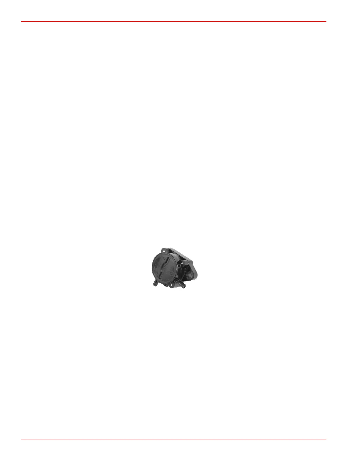
Fuel Pump
The fuel pump is a mechanically driven diaphragm pump that is driven off of the camshaft via a rocker arm. The pump base
insulates the fuel pump from the heat of the cylinder head/valve cover.
Vapor Separator Tank
The vapor separator tank (VST) maintains a liquid fuel supply for the high‑pressure fuel pump and delivers pressurized fuel to
the fuel injectors at a regulated pressure. Fuel delivered from the mechanical low‑pressure fuel pump enters at the top of the
vapor separator and passes through a needle/float assembly that controls the fuel level with the VST. The high‑pressure pump
inlet is submerged below the fuel level and draws fuel in through an attached fuel filter.
The high‑pressure fuel pump is pulse‑width modulated by the ECM to deliver fuel flow in excess of the fuel volume injected in
the intake manifold by the fuel injectors. The excess fuel recirculates through the pressure relief valve within the VST.
Fuel System Operation
Page 3A-2 © 2018 Mercury Marine 90-8M0125265 eng NOVEMBER 2017
 Loading...


