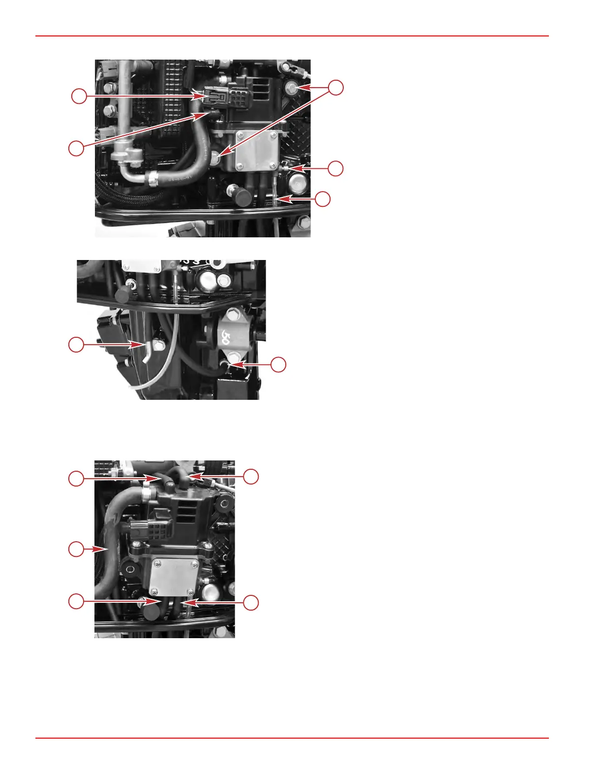
7. Remove the hose clamp securing the low‑pressure fuel supply hose to the assembly.
a - Hose clamp securing the low‑pressure fuel
supply hose
b - High‑pressure fuel pump wire harness
connector
c - Screws (2)
d - VST drain screw
e - VST drain hose
8. Disconnect the fuel cooler water supply and water pump indicator hoses from the fittings located in the driveshaft housing.
a - Water pump indicator hose fitting
b - Fuel cooler water supply hose fitting
9. Remove the Oetiker® clamp securing the high‑pressure fuel hose to the VST, and remove the fuel hose from the VST.
10.
Remove the two vent hoses from the top of the VST assembly.
11. Pull the entire assembly away from the engine, carefully pulling the two fuel cooler water hoses through the holes in the
midplate.
a - VST vent hoses
b - Fuel cooler water supply hose
c - Fuel cooler drain hose (water pump indicator hose)
d - High‑pressure fuel hose (to fuel rail)
Service Procedures
Page 3C-12 © 2018 Mercury Marine 90-8M0125265 eng NOVEMBER 2017
 Loading...


