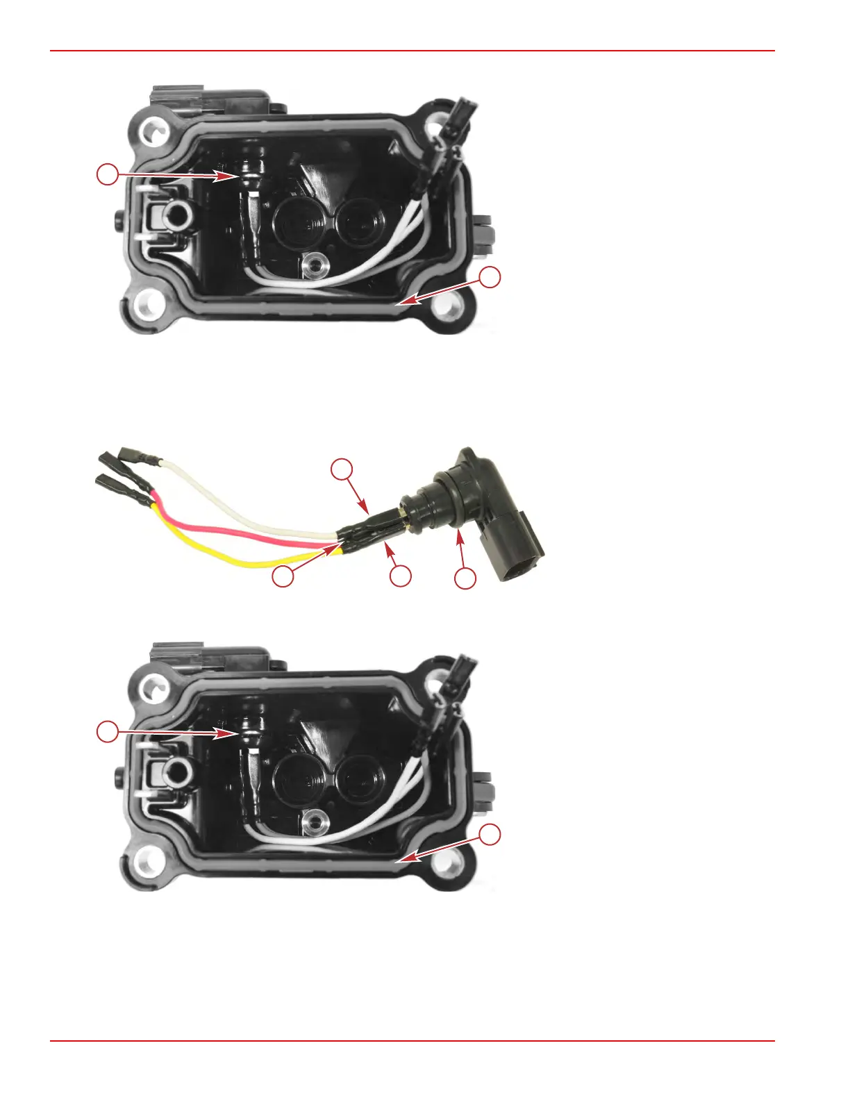
8. Remove the seal from the cover, and discard.
a - Clip
b - Seal
VST Reassembly
1.
Ensure that the O‑ring is in place on the fuel pump electrical connector, feed the red, yellow, and white wires through the
opening on the top of the VST cover, and firmly seat the connector in position.
NOTE: When viewing the electrical connector from the terminal side, the clockwise order of the wires should be white,
yellow, and red.
Fuel pump electrical connector
a - Spade connector for white wire
b - Spade connector for yellow wire
c - Spade connector for red wire
d - O‑ring
2. Secure the connector with the clip.
3.
Place a new seal in the bottom of the VST cover.
a - Clip
b - Seal
4. Place a new O‑ring onto the check valve, and insert the check valve into the VST cover.
5.
Ensure that the fuel pump wires route outside of the screw boss, and secure the check valve with the clamp and screw.
6. Attach the white, yellow, and red wires to the fuel pump.
Service Procedures
Page 3C-14 © 2018 Mercury Marine 90-8M0125265 eng NOVEMBER 2017
 Loading...


