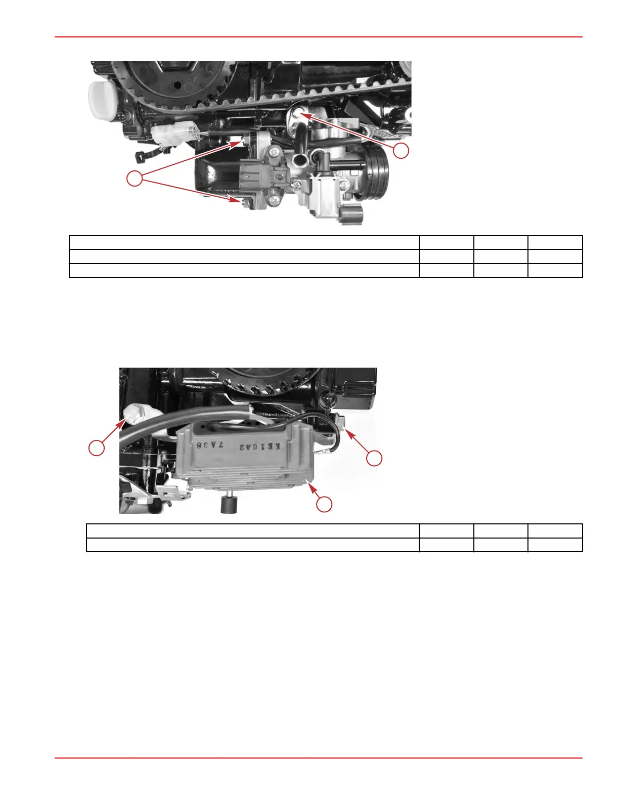
4. Install the throttle body, and secure it with two nuts and washers. Tighten the nuts to the specified torque.
a - Dipstick extension tube screw
b - Throttle body nuts
Description Nm lb‑in. lb‑ft
Dipstick extension tube screw 6.0 53.1 –
Throttle body nuts 6.0 53.1 –
Electrical Component Installation
IMPORTANT: This procedure assumes that all components are in the state as removed in Electrical Component Removal
(for example, the voltage regulator/rectifier is installed on its mounting bracket). If any additional disassembly was performed,
refer to the appropriate service procedure for reassembly.
1.
Electric start models: Install the voltage regulator/rectifier and bracket, using two screws with washers. Tighten the screws
to the specified torque.
a - Bracket screws (2)
b - Voltage regulator/rectifier
Description Nm lb‑in. lb‑ft
Voltage regulator/rectifier bracket screws 6.0 53.1 –
2. Power tilt models: Install the tilt relay/start solenoid bracket onto the engine, using two screws. Tighten the screws to the
specified torque.
Cylinder Block/Crankcase
90-8M0125265 eng NOVEMBER 2017 © 2018 Mercury Marine Page 4A-31
 Loading...


