• Turn the driven gear and align the dot on the driven gear with the timing mark on the cylinder block.
•
Adjust the intake and exhaust valve clearance for #1 cylinder.
• Turn the crankshaft 360° and align the second dot on the driven gear with the timing mark on the cylinder block.
• Adjust the intake and exhaust valve clearance for #2 cylinder.
• Tighten the locknuts to the specified torque.
IMPORTANT: When tightening locknuts, hold the adjusting screw with a square drive socket or adjustable wrench to
prevent it from moving.
Description Nm lb‑in. lb‑ft
Locknut 7.0 62 –
5. Install the following components:
•
Cylinder head cover. Refer to Cylinder Head Installation.
•
Connect inlet and outlet fuel pump hoses. Refer to Section 4A ‑ Powerhead Installation.
•
Camshaft gear cover/vent tank. Refer to Section 3C ‑ Camshaft Gear Cover/V
ent Tank.
• Air box and recoil starter.
• It is easiest to install these two items together.
•
Refer to Section 8A ‑ Recoil Starter and Section 3C ‑ Air Box Installation.
• Spark plugs.
Cylinder Head Removal
1.
Remove the powerhead from the driveshaft housing. Refer to Section 4A ‑ Powerhead Removal.
IMPORTANT: The timing belt is removed during powerhead removal. Ensure that the engine timing is set correctly before
removing the cylinder head, to avoid damaging any of the valves.
2.
Remove the electrical components from the cylinder head. Refer to Section 4A ‑ Electrical Component Removal.
NOTE: To service only the cylinder head, it is not necessary to completely remove all electrical components from the
powerhead. Refer to the note in the electrical component removal procedure.
3. Remove the spark plugs.
4.
Remove the throttle body from the cylinder head. Refer to Section 4A ‑ Throttle Body Removal.
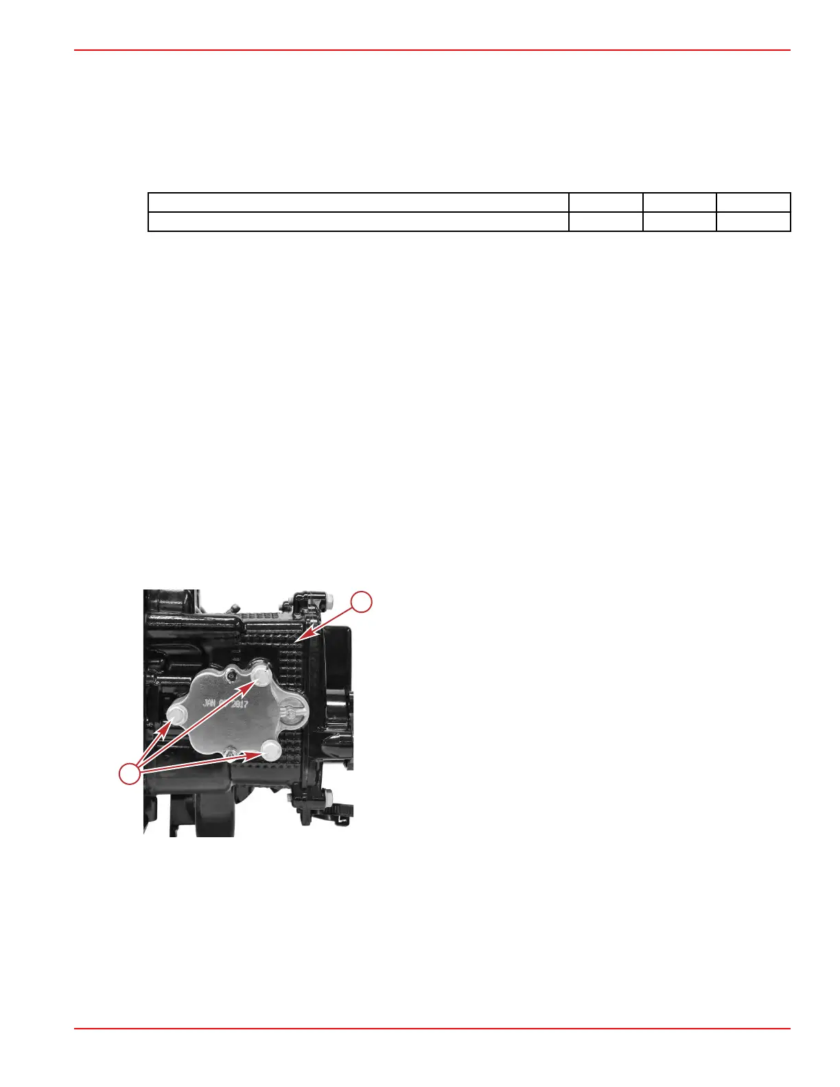
5. Remove the three screws holding the oil pump to the cylinder head.
a - Underside of cylinder head
b - Screws (3)
6. Remove the camshaft gear retaining screw.
Cylinder Head
90-8M0125265 eng NOVEMBER 2017 © 2018 Mercury Marine Page 4B-11
 Loading...


