12. Install the cap.
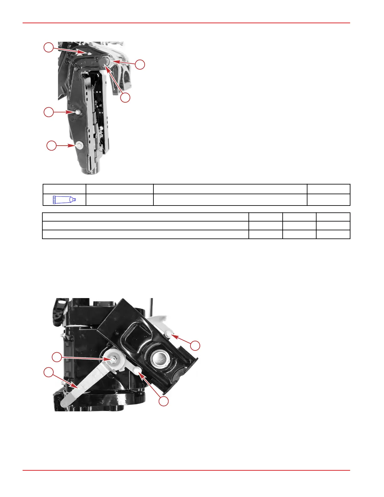
a - Ground cable screw
b - Nut
c - Cap
d - Lower pivot pin screw (M8 x 20) and washer
e - Tilt lock pin, locknut, and washer
Tube Ref No. Description Where Used Part No.
95
2-4-C with PTFE Tilt tube washer 92-802859A 1
Description Nm lb‑in. lb‑ft
Lower pivot pin screw (M8 x 20) 13 115 –
Tilt tube locknut 24.0 – 17.7
Steering Arm Removal
1.
Separate the powerhead/driveshaft housing/gearcase assembly from the clamp bracket/swivel bracket/steering arm
assembly. Refer to Powerhead/Midsection Assembly Separation.
2. For tiller handle models, remove the copilot hardware:
a. Remove one locknut to remove the copilot handle.
b. Remove two screws with washers to remove the remaining copilot components from the swivel bracket.
a - Copilot handle
b - Locknut
c - Screw with washer
Clamp/Swivel Bracket and Driveshaft Housing
Page 5A-30 © 2018 Mercury Marine 90-8M0125265 eng NOVEMBER 2017
 Loading...


