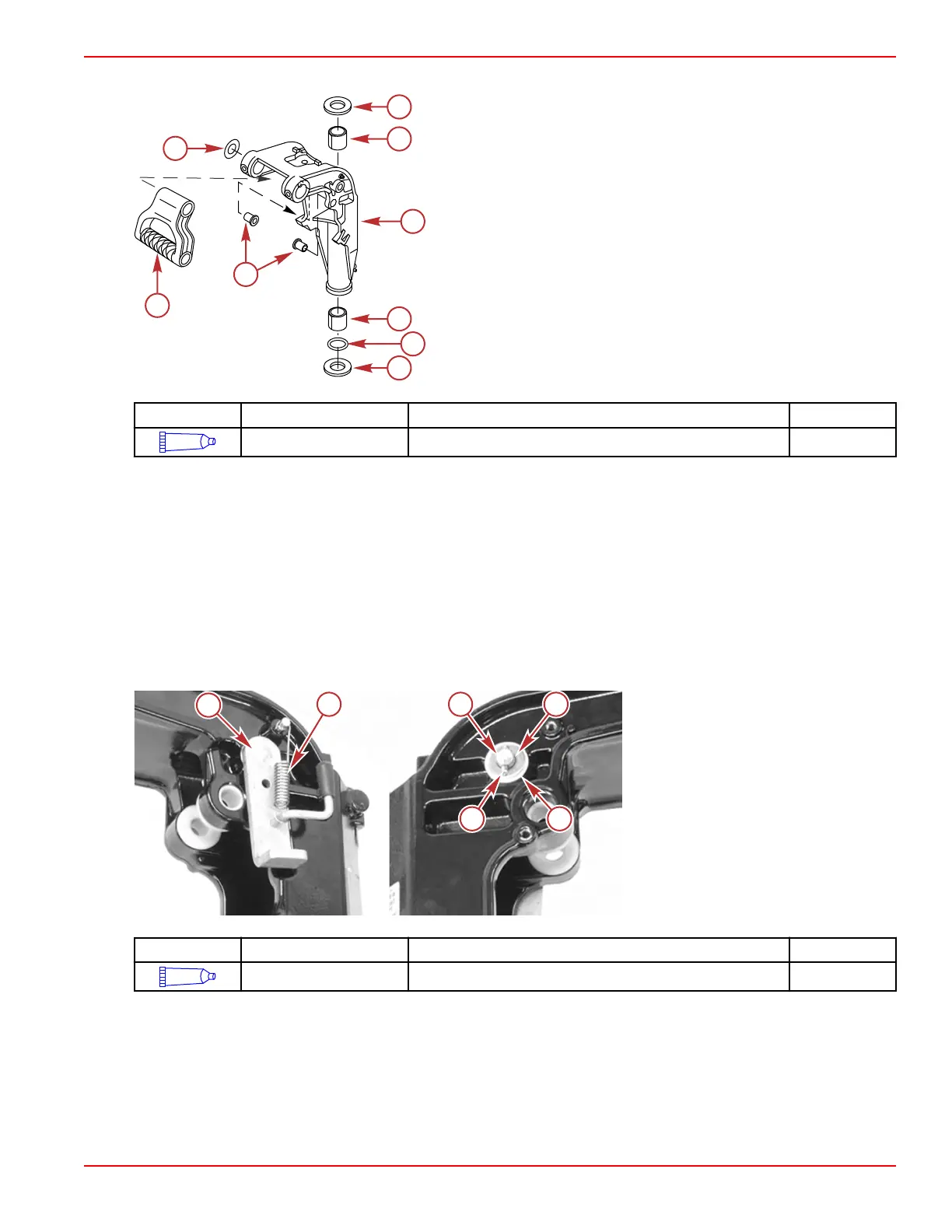
5. Install the bushings into the swivel bracket.
Power tilt model
a - Thrust plate
b - Swivel bracket bushing (2)
c - Swivel bracket
d - O‑ring
e - Lower pivot bushings (2)
f - Carrying handle
g - Washer (2)
Tube Ref No. Description Where Used Part No.
95
2-4-C with PTFE Swivel bracket bushings 92-802859A 1
Tilt Lock Lever
1.
Remove the tilt spring from the swivel bracket.
2. Remove the spring pin from the tilt lock pin.
3. Remove the tilt lock pin.
4. Inspect the bushings. Replace if necessary.
5. Apply 2‑4‑C with PTFE to the pin and bushings.
6. Install the bushings and pin.
7. Install a washer onto the tilt lock pin.
8. Install the spring pin through the tilt lock pin.
9. Install the tilt spring onto the swivel bracket.
Port side shown at left, starboard
shown at right
a - Tilt lock lever
b - Tilt spring
c - Tilt lock pin
d - Washer
e - Bushing (2)
f - Spring pin
Tube Ref No. Description Where Used Part No.
95
2-4-C with PTFE Tilt pin and bushings 92-802859A 1
Swivel Bracket Installation
1.
Clean the tilt tube and clamp brackets.
2. Insert the tilt tube through the port clamp bracket.
3. Install a washer onto the tilt tube.
4. Install the carrying handle.
Clamp/Swivel Bracket and Driveshaft Housing
90-8M0125265 eng NOVEMBER 2017 © 2018 Mercury Marine Page 5A-33
 Loading...


