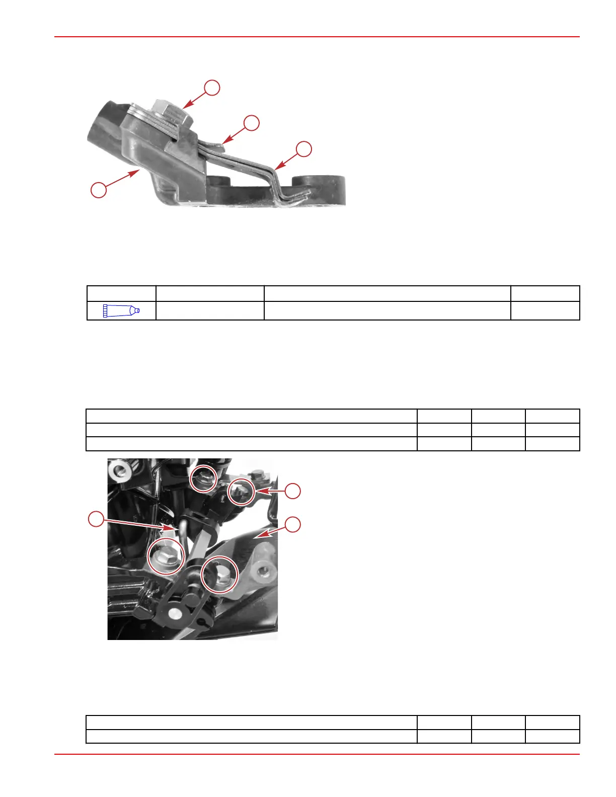
Shift Detent
Inspect the shift detent hardware. Replace any worn or damaged components.
a - Shift detent springs
b - Short detent spring
c - Screw
d - Port shift lever bracket
Throttle and Shift Linkage Installation
1.
Ensure the gearcase is in neutral.
2. Install the vertical shift shaft, if it was removed.
3. Apply 2‑4‑C with PTFE to the shift shaft assembly detents and contact surfaces.
Tube Ref No. Description Where Used Part No.
95
2-4-C with PTFE Shift shaft assembly detents and contact surfaces 92-802859A 1
4. Install the shift shaft lever, being certain to engage the vertical shift shaft.
5.
Ensure that the shift detent hardware is assembled on the port shift shaft lever bracket. Refer to Shift Detent.
6.
Secure the shift shaft lever with two brackets and four screws.
7. Ensure that the front cowl properly engages the midplate and the vertical shift shaft boot.
NOTE: If the front cowl was removed from the shift lever brackets, install it now.
8. Tighten the four shift shaft lever bracket screws (two per bracket) and the shift detent screw to the specified torque.
Description Nm lb‑in. lb‑ft
Shift shaft lever bracket screws 6.0 53.1 –
Shift detent screw 6.0 53.1 –
a - Shift shaft lever bracket screws (4)
b - Front cowl
c - Vertical shift shaft
9. Electric start models:
a. Install the neutral safety switch.
b.
Install the starter motor. Refer to Section 2B ‑ Starter Motor Installation.
10. Install the shift link, using one screw, two washers (one each side), and one bushing. Tighten the screw to the specified
torque.
Description Nm lb‑in. lb‑ft
Shift link screw 6.0 53.1 –
Throttle and Shift Linkage
90-8M0125265 eng NOVEMBER 2017 © 2018 Mercury Marine Page 7A-9
 Loading...


