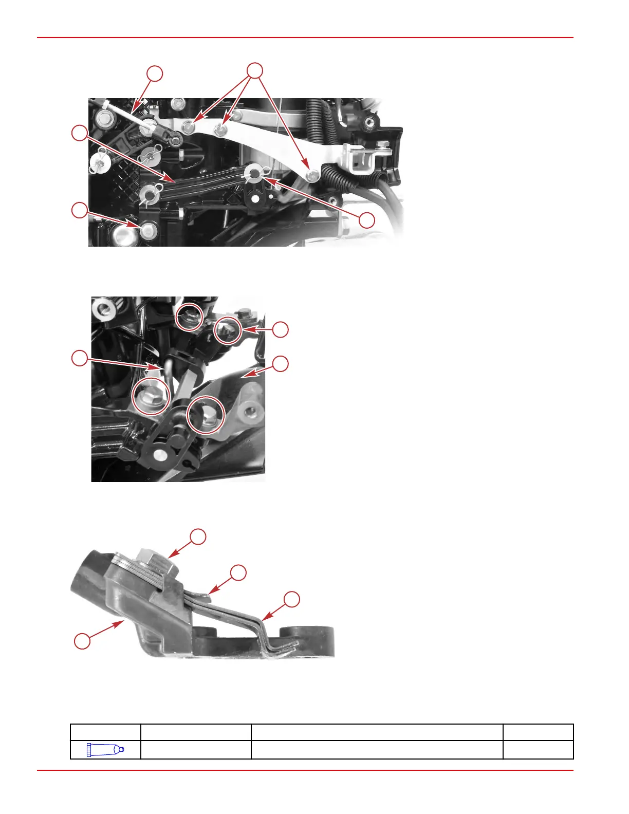
10. Remove one screw, two washers, and a bushing to remove the shift link from the engine.
a - Throttle link
b - Throttle and shift bracket screws
(3)
c - Retaining clip and washer
d - Screw, two washers, and bushing
e - Shift link
11.
Remove the starter motor. Refer to Section 2B ‑ Starter Motor Removal.
12.
Remove the four screws securing the two shift lever shaft brackets. The front cowl will come loose with the brackets.
13. Disconnect the upper shift shaft from the shift lever, and remove the shift lever shaft assembly.
a - Shift lever bracket screws (4)
b - Front cowl
c - Upper shift shaft
Shift Detent
Inspect the shift detent hardware. Replace any worn or damaged components.
a - Shift detent springs
b - Short detent spring
c - Screw
d - Port shift lever bracket
Throttle and Shift Linkage Installation
1.
Install the upper shift shaft, if it was removed.
2. Apply 2‑4‑C with PTFE to the shift shaft assembly detents and contact surfaces.
Tube Ref No. Description Where Used Part No.
95
2-4-C with PTFE Shift shaft assembly detents and contact surfaces 92-802859A 1
Throttle and Shift Linkage
Page 7A-12 © 2018 Mercury Marine 90-8M0125265 eng NOVEMBER 2017
 Loading...


