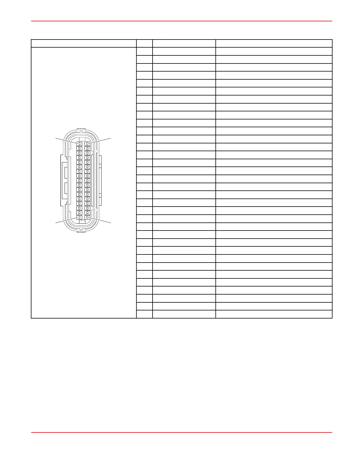
Engine Control Module Pinout
Connector Pin Wire Color Function
1 Orange Ignition coil
2 Yellow Warning horn
3 Black/red Stator coil H
4 Blue 12 VDC
5 Blue Stator coil L
6 Green/orange MAP sensor
7 Red/white Sensor power 5 VDC
8 Red/white CPS (signal)
9 Black CPS (ground)
10 Black Ground
11 White Diagnostics (Rx)
12 Red/white Communication power 5 VDC
13 Red Battery input (diagnostics)
14 Blue Boot mode
15 Black/green VST W
16 Black/yellow VST V
17 Black/white VST U
18 Light green/red Injector 1
19 Light green/black Injector 2
20 Green/red IAC valve
21 Gray Tachometer
22 N/A Not used
23 Blue/white TPS
24 Green/yellow ECT sensor power
25 Green/white MAT sensor
26 N/A Not used
27 Black/blue Sensor ground
28 Yellow Diagnostics (Tx)
29 Brown Stop switch
30 Brown/white Oil pressure switch power supply
31 N/A Not used
32 N/A Not used
33 Light green LED
34 N/A Not used
Fault Codes
Mercury Universal Fault Codes
Mercury universal fault codes help ensure uniformity in fault reporting in control modules. It also ensures that boat operators
receive consistent information and instruction, such as Service Engine Soon, Reduce Engine Speed, and others in response
to specific faults.
General Troubleshooting
90-8M0125265 eng NOVEMBER 2017 © 2018 Mercury Marine Page 1E-11
 Loading...


