90-823225--1 10965E-16 - ELECTRONIC FUEL INJECTION (MULTI-PORT AND THROTTLE BODY)
If the TP circuit is open, the ECM will set a Code 21.
If the TP circuit is shorted, and a trouble Code 21 will
be set. A problem in any of the TP circuits will set a
Code 21. Once a trouble code is set, the ECM will use
a default value for TP.
DISTRIBUTOR REFERENCE (DIST REF)
The distributor reference (engine speed signal) is
supplied to the ECM by way of the “Dist Ref Hi” line
from the High Energy Ignition (HEI). This pulse
counter type input creates the timing signal for the
pulsing of the fuel injectors, as well as the Ignition
Control (IC) functions. This signal is used for a num-
ber of control and testing functions within the ECM.
DISCRETE SWITCH INPUTS - POWER
REDUCTION MODE
(1996 AND OLDER MODELS
)
Several discrete switch inputs are utilized by the sys-
tem to identify abnormal conditions that may affect
engine operation. Pull-down switches are used in
conjunction with the ECM to detect critical conditions
to engine operation.
If a switch changes state from its normal at rest posi-
tion, that is normally open to closed, the ECM senses
a change in voltage and responds by entering power
reduction mode.
This engine protection feature allows the operator full
engine power up to 2800 RPM, but disables half of
the fuel injectors above 2800 RPM until the engine
RPM drops to 1200 RPMS.
This feature allows the operator a comfortable ma-
neuvering speed while removing the possibility of
high RPM engine operation until the problem is cor-
rected.
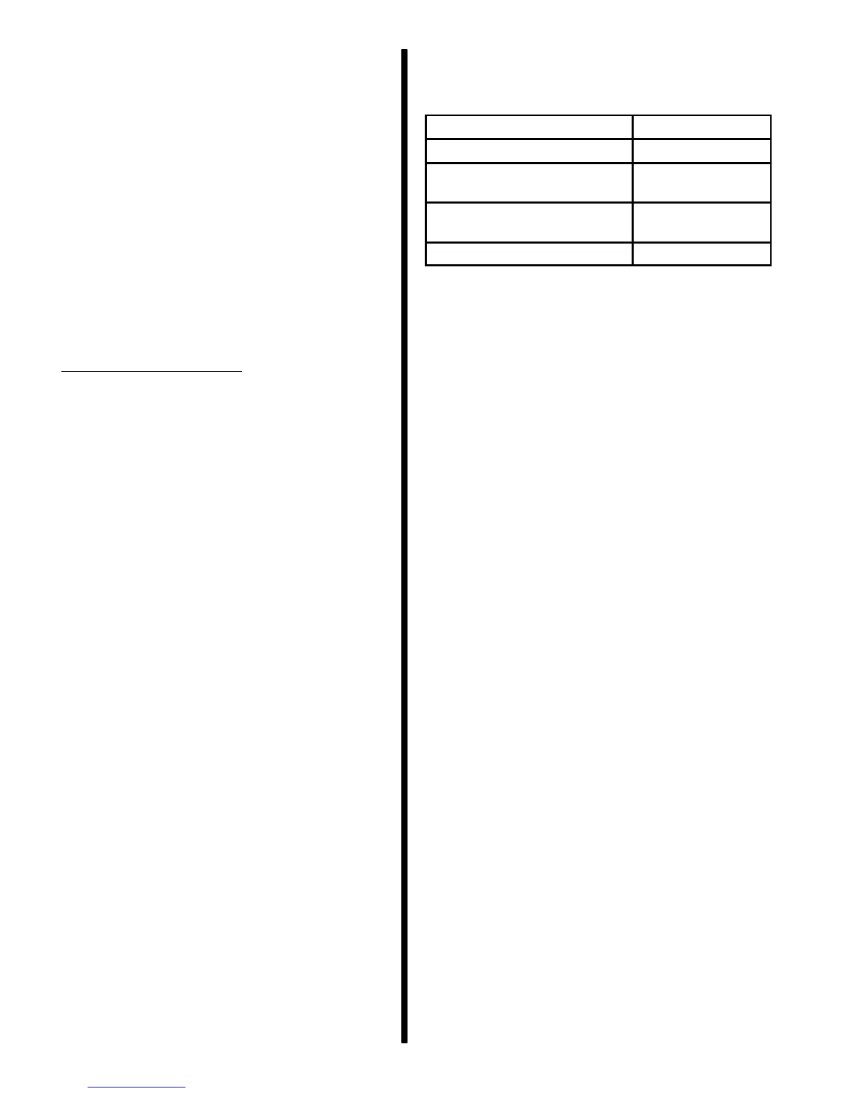
Switches which are used with the Fuel Injection sys-
tem to detect critical engine operation parameters
are:
Switch
Normal State
Oil Pressure N/O
I/O Fluid Level on Stern
Drive
N/O
Transmission Temperature
on MIE Models
N/O
Engine Coolant Temperature N/O
IMPORTANT: Models equipped with multiple en-
gines must use dual engine data link kit and com-
mon ground between engine blocks. Otherwise
there will be no serial data communication be-
tween engines and the power reduction mode
will not control both engines.
• Triple (three) engine applications should connect
the outboard engines.
• Quad (four) engine applications Should link the
outer two outboard engines with one link and the
two inboard engines with another link.

 Loading...


