Mercury Security Corporation © 2011 EP1502 DOC 10107-0031 REV 1.05 Page 2
3. EP1502 Wiring and Setup:
NO: Normally Open Contact
NC: Normally Closed Contact
NO: Normally Open Contact
NC: Normally Closed Contact
NO: Normally Open Contact
NC: Normally Closed Contact
NO: Normally Open Contact
NC: Normally Closed Contact
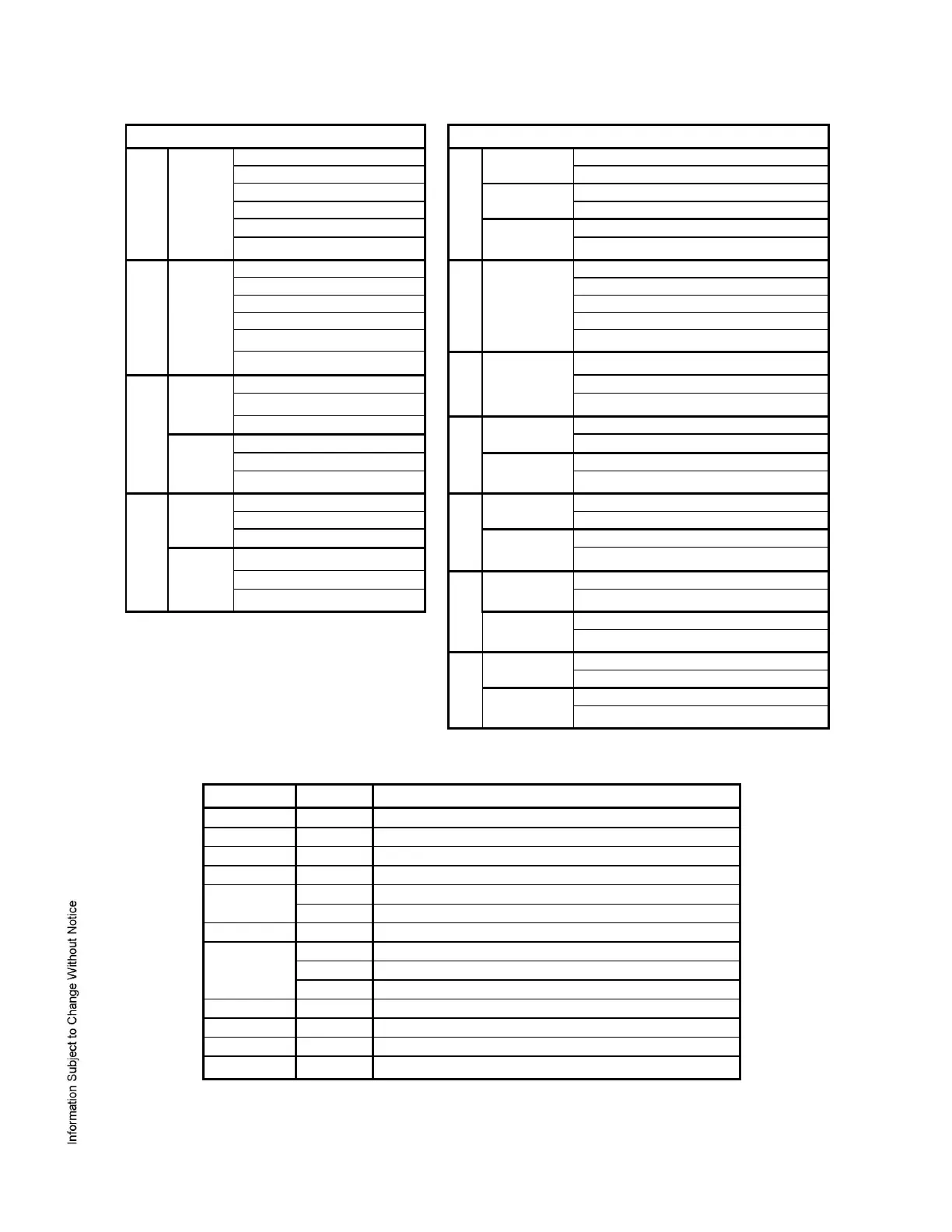
Jumpers:
The EP1502 processor hardware interface is configured using jumpers to setup the port interface and end
of line termination.
10Base-T/100Base-Tx Ethernet Connection (Port 0)
Port 2 RS-485 EOL Terminator is Off
Port 2 RS-485 EOL Terminator is On
Reader Power Select. See Note 1
VIN "Pass Through" to Reader Ports
Remote Status Led #1. See Note 2
Remote Status Led #2. See Note 2
Remote Status Led #3. See Note 2
Remote Status Led #4. See Note 2
Note 1: The input power (VIN) must be 20 Vdc minimum if the 12 Vdc selection is to be used.
Note 2: Observe POLARITY connection to LED. External current limiting is not required.
 Loading...