BEFORE
YOU BEGIN
10
INTRODUCTION
IMPORTANT
PRECAUTIONS
ASSEMBLY
BEFORE
YOU BEGIN
ELLIPTICAL
OPERATION
LIMITED
WARRANTY
TROUBLESHOOTING
& MAINTENANCE
CONDITIONING
GUIDELINES
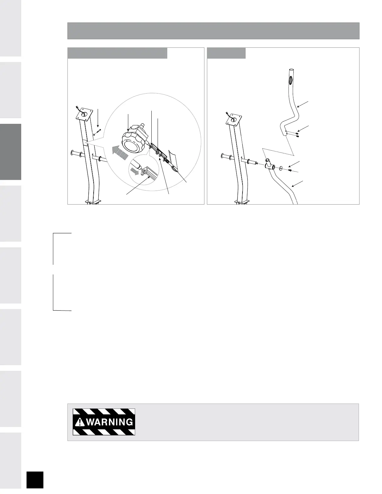
ASSEMBLY STEP 4
PRE-ATTACHED BOLTS AND WASHERS
LOWER HANDLEBAR
PRE-ATTACHED SET SCREWS
UPPER HANDLEBAR
F) Remove PRE-ATTACHED BOLT & WASHERS from CONSOLE MAST.
G) Slide LOWER HANDLEBARS onto CONSOLE MAST and attach by re-inserting PRE-ATTACHED SET SCREWS.
H) Slide UPPER HANDLEBARS onto LOWER HANDLEBARS. Secure UPPER HANDLEBARS to LOWER HANDLEBARS
using PRE-ATTACHED SET SCREWS.
After handlebars are assembled they will rotate freely – be cautious. Until the
machine is fully assembled, do not grab the handlebars for support.
RESISTANCE
KNOB
TENSION WIRE RESISTANCE
KNOB BRACKET
TENSION
CABLE
PRE-INSTALLED
BOLT & WASHER
TOP KEY HOLE
BOTTOM KEY HOLE
NOTE: There is NO hardware bag for this step. All hardware is pre-installed.
A) Pull TENSION CABLE out from square hole in console mast.
B) Turn RESISTANCE KNOB to highest resistance setting. Place the TENSION WIRE into the BOTTOM KEY
HOLE on the RESISTANCE KNOB BRACKET.
C) While holding the RESISTANCE KNOB BRACKET, pull the RESISTANCE KNOB up to slide it into the TOP KEY
HOLE position on the RESISTANCE KNOB BRACKET.
D) Once the TENSION WIRE is in position, turn the RESISTANCE KNOB to the lowest resistance setting.
E) Slide RESISTANCE KNOB & BRACKET into the CONSOLE MAST and attach using PRE-INSTALLED BOLT &
WASHER.
STEPS A-E (710E ONLY) STEPS F-H
710E ONLY