MI 3102(H) BT EurotestXE Measurements
56
5.8 Earth resistance
Earth resistance is one of the most important parameters for protection against electric shock.
Main earthing arrangements, lightning systems, local earthings, soil resistivity, etc can be
verified with the earthing resistance test. The measurement conforms to the EN 61557-5
standard.
The Earth resistance main function is divided into three sub-functions:
3-wire earth resistance test RE for standard earth resistance tests with two earthing
rods.
Contactless earth resistance test with two current clamps (also recommended in IEC
60364-6 for urban areas), for measuring resistance to earth of individual earthing rods.
Specific earth resistance.
See chapter 4.2 Function selection for instructions on
key functionality.
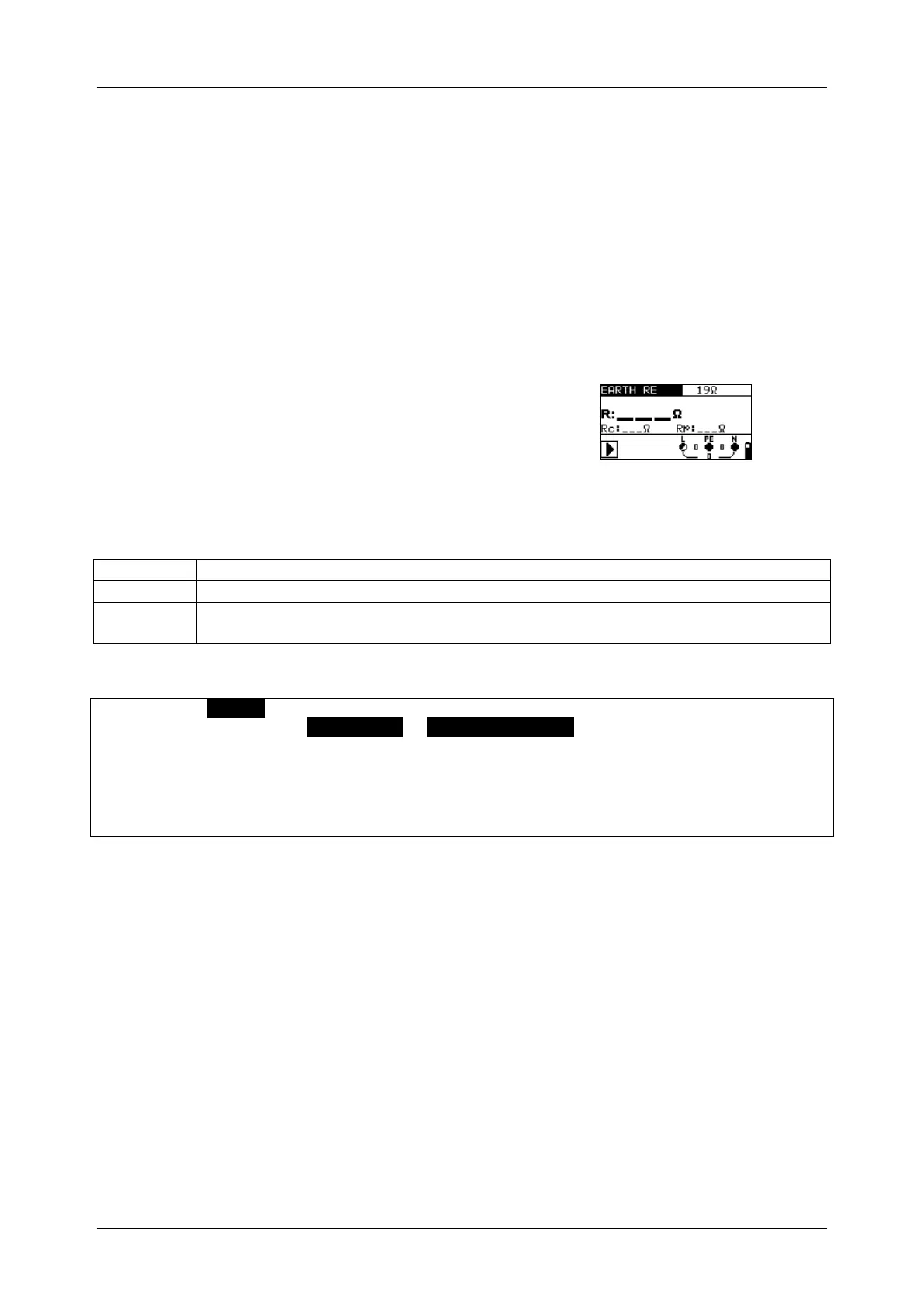
Figure 5.35: Earth resistance
Test parameters for earth resistance measurement
Test configuration [EARTH RE, two clamps, ]
Maximum resistance [OFF, 1 ÷ 5 k]
In sub-function only:
Distance between probes [0.1 m ÷ 30.0 m] or [1 ft ÷ 100 ft]
Earth resistance measurements, common measurement procedure
Select EARTH function using the function selector keys.
Set sub-function to EARTH RE or EARTH 2 CLAMPS using UP / DOWN keys.
Enable and set limit value (optional).
Connect test leads to the instrument.
Connect the item to be tested (see Figure 5.36, Figure 5.37 and Figure 5.39).
Press the TEST key to perform the measurement.
Store the result by pressing the MEM key (optional).
 Loading...