MI 3122 Smartec Z Line-Loop / RCD Connector panel
12
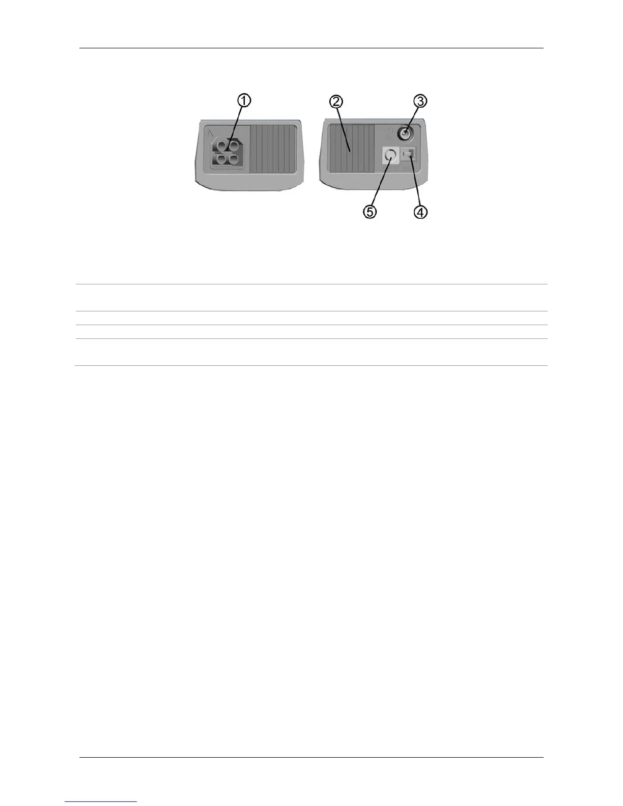
3.2 Connector panel
Figure 3.2: Connector panel
Legend:
1 Test connector Measuring inputs / outputs, connection of measuring cables.
2 Protection cover
Protects from simultaneous access to test connector and power
supply adapter socket / communication connectors.
3 Charger socket Connection of power supply adapter.
4 USB connector Communication with PC USB (1.1) port.
5 PS/2 connector
Communication with PC serial port and connection to optional
measuring adapters.
Warnings!
Maximum allowed voltage between any test terminal and ground is 600 V!
Maximum allowed voltage between test terminals is 600 V!
Maximum short-term voltage of external power supply adapter is 14 V!
 Loading...