Doc# 1231558 • REV C (November 2017) Page 17 of 20
• Cool-Down Period
If the circuit acvang the startup delay leaves the voltage connuously applied (as
is typical), the thermistor will remain hot unl voltage is removed, such as follow-
ing a machine trip. Thus, when the thermistor is not allowed to cool to its ambient
surroundings, it will shorten the startup delay.
• Immediate Restart
If a restart is required immediately following a trip, the thermistor may be so hot
that the switch cannot be immediately reset using the remote reset funcon. In
such situaons, it will be necessary to either manually reset the switch or wait for
the thermistor to cool suciently. Alternavely, it may be desirable to modify the
machinery control logic such that voltage is only applied to the reset terminals for
the duraon of the factory pre-set delay, ensuring that the thermistor circuit is only
energized at startup.
• Current Flow
The amount of current owing through the thermistor will be a funcon of the volt-
age applied, the thermistor’s resistance, and the resistance elsewhere in the circuit.
Loose, intermient, or corroded wiring connecons can increase resistance and result
in a longer startup delay interval. If the resistance is too great, the reset coil will not
energize at all due to insucient current. Insucient voltage and/or current can also
be a problem. Be certain that the coil voltage rang (ordering opon D) matches the
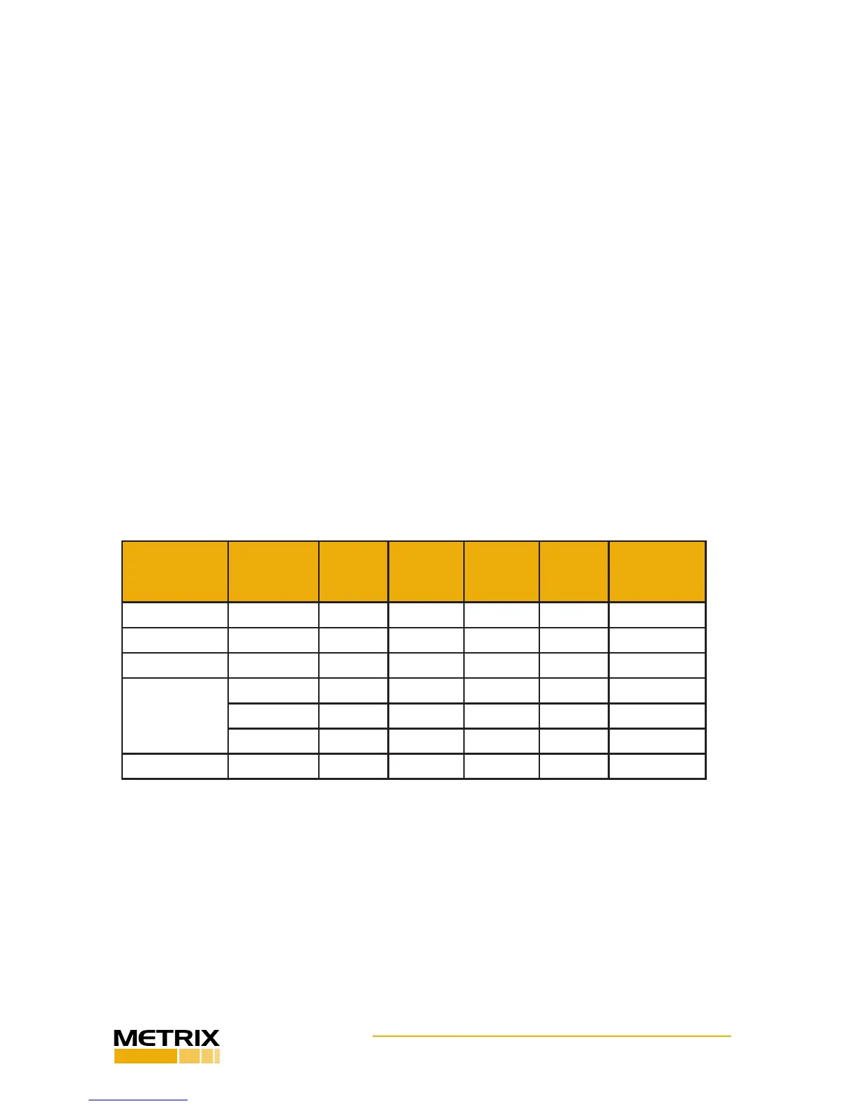
voltage and current your circuit supplies. See Table 1 on the following page.
Opon D
(coil voltage)
Opon C
(coil holding
force)
Rated
Voltage
Min
Voltage
Max
Voltage
Min
Current
Max Power
Consumpon
None (D=0) All N/A N/A N/A N/A N/A
115 Vac (D=1) All 115 Vac 103.5 Vac 126.5 Vac 1.24 A 287.5 W
230 Vac (D=2) All 230 Vac 207 Vac 253 Vac 0.32 A 230 W
24 Vdc (D=3) 5 g (C=1) 24 Vdc 22.8 Vdc 25.3 Vdc 1.58 A 60 W
2 g (C=2) 24 Vdc 22.8 Vdc 25.3 Vdc 1.18 A 28.8 W
10 g (C=3) 24 Vdc 22.8 Vdc 25.3 Vdc 2.88 A 72 W
115 Vdc (D=4) All 115 Vdc 103.5 Vdc 126.5 Vdc 1.20 A 207 W
Table 1: Reset / Startup Delay Coil Electrical Characteriscs
5.3 Coil Consideraons
5.3.1 Coil Hold Strength
The reset / startup delay coil is sized to provide a specied holding strength (opon C), al-
lowing the startup delay feature to hold the switch in its untripped state even in the pres-
ence of high vibraon encountered during machine startup. If the reset coil supplied will
not hold the switch in an untripped state during startup, it may be the wrong size. Refer
to Table 1 and consult the factory for assistance.
 Loading...
