Document 9162 Manual - ST5484E 2-Wire Seismic Vibration Transmitter Page 5 of 7
Rev. T (Oct 2013)
6. Typical Transmitter Placement
The ST5484E measures seismic vibration (i.e., vibration velocity) at the
attachment point on the machine, using engineering units of in/s (inches
per second) or mm/s (millimeters per second) depending on which ordering
option has been selected. The transmitter’s sensitive direction is through
the long axis of its cylindrical body. It will not measure side-to-side motion
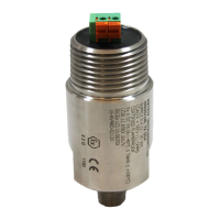
Typical transmitter mounting for casing vibration measurements is in the
horizontal direction at the bearing housings as depicted in Figures 2. The
horizontal direction usually incurs more vibration because most machines
are more compliant in the horizontal axis than the vertical axis (i.e., the
machine’s foundation constrains vertical vibration more than horizontal
vibration). Figure 2
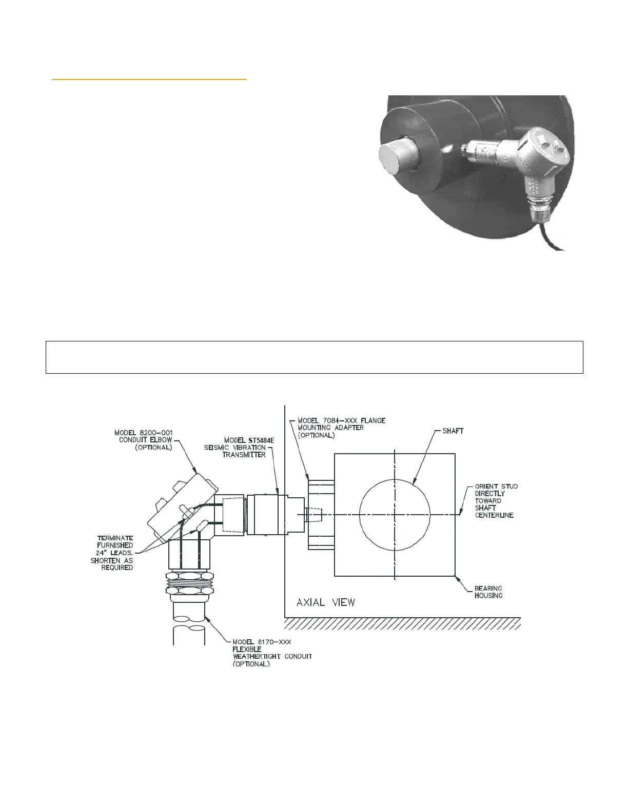
A horizontal mounting arrangement is also depicted in Figure 3, but with additional detail showing typical accessories. When
flying leads are ordered, a 24 inch or 72 inch length may be specified using ordering option D. These leads may be cut to
length in the field and then spliced to field wiring as shown in Figure 3.
NOTE: Hazardous area locations do not allow a splice at the location shown in Figure 3. Instead, the splice must be made in a
second conduit hub (meeting splicing requirements) located at the end of flexible conduit.
 Loading...