Page 3
1. After installing the charging station as described on the Page 1 install the supplied current measuring
transformers (CT) on the house/building main power supply input and connect them to Micro EVSE 3
DYNAMIC WiFi EV charge controller as shown on the ME3-1 or/and ME3-2 drawings in the attachment.
2. Switch ON charging station power supply.
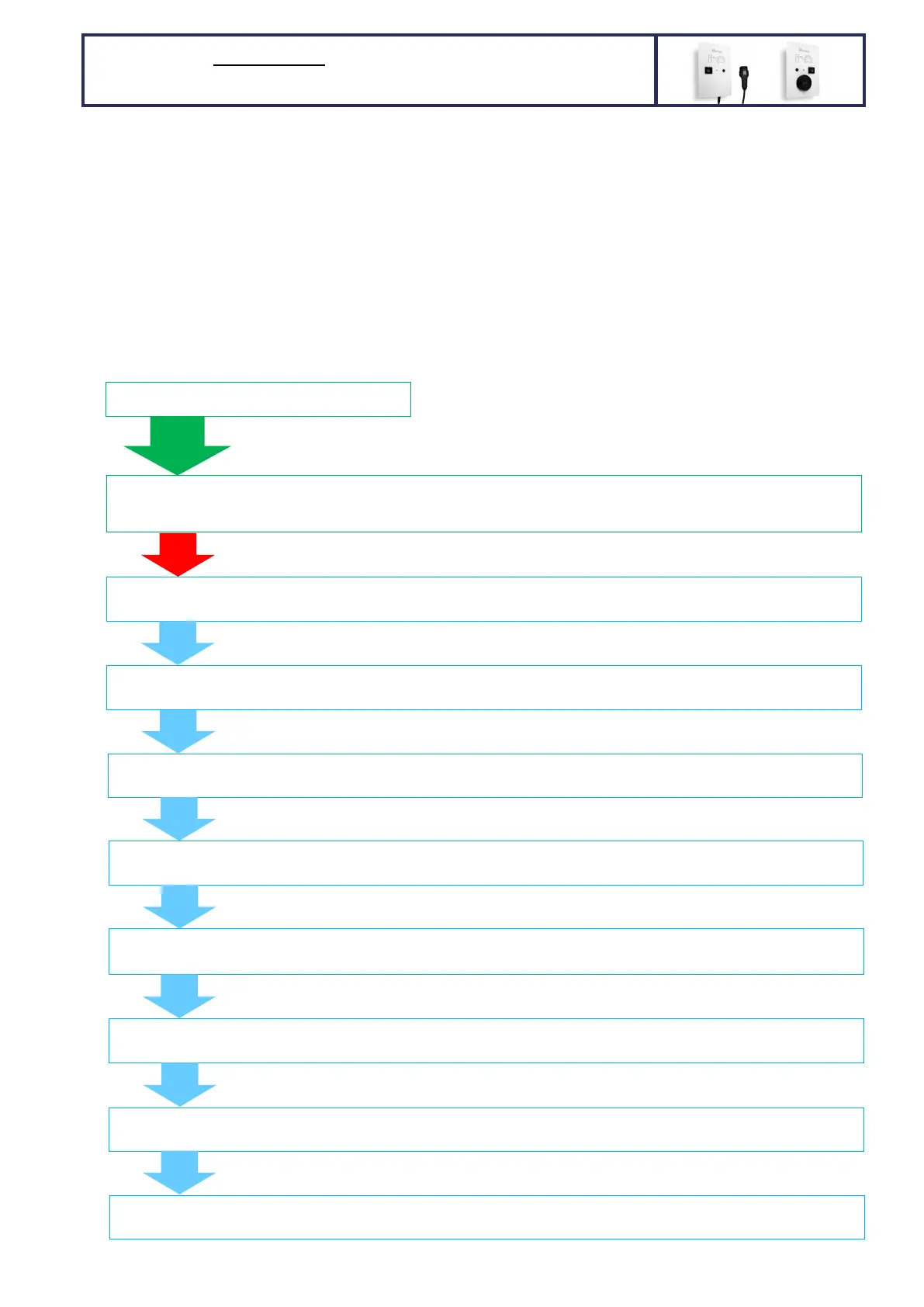
3. Set the needed parameters via front PUSH BUTTON: when no car is connected push the charging station front
button (blue status LED is switched OFF) and keep it pressed. After 5 seconds the status LED starts to blink.
The first set of blinks in this step is not important as this just limits/sets the user desired charging limit
(described on the first page). When the status LED stops blinking keep the button pressed for additional 30
seconds. After 30 seconds the blue status LED will start to blink again. Releasing the front push button after
certain LED blink sets the new value for desired parameter.
The following chart describes what can/shall be set:
5s
PRESS the BUTTON and keep it pressed
General NOTE: you can set only 1 parameter at a time. Setting
desired parameter does not have any influence on other
parameters. The set values stay saved in the memory
permanently (power loss doesn’t delete settings).
Wait
30s
5 or 8 LED blinks - Setting the charging current: 1 to 8 LED blinks represent 6A, 8A, 10A, 13A, 16A, 20A, 25A, 32A
charging current; 6,7,8 LED blinks exist only for 32A capable charging stations (1f/3f)
3 LED BLINKS - Solar/wind/hydro power plant phases: 1 to 3 LED blinks represent 1, 2 or 3 phase power plant grid connection.
Default setting: 3 phases
Wait
5s
Wait
5s
80 LED BLINKS - House main fuse rating: 1 to 80 LED blinks represent 1 to 80 A main fuse rating.
Default setting: 35 A
Wait
5s
5 LED BLINKS – Charging current regulation loop delay: 1 to 5 LED blinks represent 1 to 5 seconds charging current regulation
loop delay. Default setting: 2 seconds (shall not be changed!)
Wait
5s
2 LED BLINKS – ACTIVATION/ENABLE signal (RFID, RF remote, etc) or ACTIVATION via WiFi app. for charging start: 1 to 2 LED
blinks; 1 blink = activation not required, 2 blinks = activation required. Default setting: 1 = activation not required
Wait
5s
2 LED BLINKS – wireless main fuse protection dynamic charging RF receiver activation: 1 to 2 LED blinks; 1 blink = wireless OFF,
2 blinks = wireless ON. Default setting: 1 = wireless OFF
Wait
5s
25 LED BLINKS – Wireless RF receiver channel: 1 to 25 LED blinks that represent 1 to 25 RF channels.
Default setting: channel 1
3 LED BLINKS - House grid connection phases: 1 to 3 LED blinks represent 1, 2 or 3 phase grid connection.
Default setting: 3 phases
30 LED BLINKS – station ID (identification) that is used for optimized and prioritized wireless main fuse protection dynamic
of more than 1 charging station:
that represent station’s IDs from
Wait
5s
HARDWIRED 1 or 3-phase MAIN FUSE protection DYNAMIC
charging with 1 WALL MOUNTED charging station per fuse
 Loading...