Do you have a question about the MFJ Enterprises MFJ-9015 and is the answer not in the manual?
Highlights the MFJ-9015's simple setup and operation, comparing it to complex multi-band radios.
Details the high sensitivity of the receiver, mentioning features like a four-pole front-end filter and double-balanced mixing.
Discusses the tight 750-Hz CW-bandwidth crystal filter and optional narrow audio filter for improved selectivity.
Describes the VFO's smooth 6:1 reduction drive, easy-to-read dial, and RIT for enhanced usability.
Covers AGC tracking, clear sidetone, instant recovery, and audio power from the speaker or phones.
Explains the transmitter's full QRP output, VSWR tolerance, adjustable T/R switching, and optional keyer module compatibility.
Suggests portable operation with accessories and notes the rugged G-10 board and aluminum cabinet construction.
Lists key receiver parameters including frequency coverage, type, IF frequency, selectivity, AGC, and sensitivity.
Details transmitter specs like keying, sidetone, RF power output, VSWR tolerance, and transmit current.
Presents a schematic block diagram illustrating the internal signal flow and major components of the transceiver.
Details the functions of connectors and switches located on the rear panel of the MFJ-9015 transceiver.
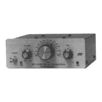
Explains the purpose of each control and indicator on the front panel of the MFJ-9015, including power, volume, and tuning.
Specifies the required power source (12-15 V @ 1.2 A) and details connector types and polarity for the MFJ-9015.
Explains how to connect mechanical keys, relay-output keyers, and optional iambic keyer modules to the transceiver.
Discusses antenna requirements, VSWR tolerance (3:1), and suggests specific 15-meter antennas and tuners.
Recommends low-impedance (8-16 Ohm) monaural headphones for optimal audio output from the transceiver.
Provides guidance on constructing and deploying coaxial-fed dipoles, inverted Vs, and full slopers for 15-meter operation.
Describes the MFJ-1770 portable folded dipole, its construction, and the built-in 50-ohm matching network.
Offers tips on maintaining antennas, including cleaning contacts, replacing hardware, and tuning for minimum SWR.
Provides strategies for successful DX operation, such as listening, calling CQ with /QRP, persistence, and using RIT.
Offers advice for new hams, including seeking assistance, understanding VFO limitations, and using the rig for code speed practice.
Troubleshooting steps for power issues, including checking the plug, power source, and polarity protection fuse.
Steps to diagnose no signal reception, checking antenna connections, propagation, and leads.
Diagnoses for lack of audio, checking headphone jack and headphone wiring for faults.
Troubleshoots erratic transmission and keying, checking key plug, keyer, and power source.
Addresses issues with key clicks on sidetone or loud sidetone, checking power source and antenna adjustment.
Diagnoses erratic transmitter behavior, focusing on checking the SWR and antenna condition.
Guides on troubleshooting receiver insensitivity or ineffective AGC, involving TP-1 and AGC pot adjustment.
Troubleshooting steps for low receiver volume or insensitivity, involving TP-2 and REG pot adjustment.
Addresses excessive VFO drift by checking temperature and the rig's surface contact.
Guides on adjusting sidetone frequency by checking and readjusting the TX FREQ trimmer.
Lists special tools, parts, and test equipment needed for performing field alignment procedures on the transceiver.
Provides step-by-step instructions for preparing the transceiver and test equipment before starting the alignment.
Details voltage checks at specific test points and the adjustments required for regulator, AGC, and RIT.
Explains how to calibrate the VFO to the correct frequency using a frequency counter and VFO CAL adjustment.
Guides on checking and aligning the BFO frequency, ensuring correct sideband and sidetone output.
Describes how to check receiver sensitivity using a signal generator and measure AGC voltage.
Details the alignment process for the transmitter bandpass filter, adjusting for peak output power.
Explains how to set the transmit mixer level for optimal RF output while avoiding spurious emissions.
Provides typical DC voltages for integrated circuits and discrete components to aid in troubleshooting.
Lists pinouts and corresponding DC voltages for integrated circuits within the MFJ-9015.
Details pinouts and typical DC voltages for bipolar and JFET transistors used in the MFJ-9015.
| Modes | CW |
|---|---|
| Type | QRP Transceiver |
| Voltage | 12-15 V DC |
| Power Supply | External DC |
| Power Output | 5W |