MFJ-862 SWR/Wattmeter Instruction Manual
1
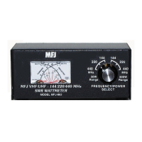
MFJ-862 VHF/UHF 144/220/440 SWR/Wattmeter
General Information
General InformationGeneral Information
General Information
The MFJ
MFJMFJ
MFJ-
--
-862
862 862
862 VHF/UHF 144/220/440 SWR/Wattmeter
VHF/UHF 144/220/440 SWR/WattmeterVHF/UHF 144/220/440 SWR/Wattmeter
VHF/UHF 144/220/440 SWR/Wattmeter measures forward and
reflected power and indicates SWR for the 144
144144
144, 220
220220
220, and 440 MHz
440 MHz440 MHz
440 MHz ham bands.
The MFJ-862 has 2 power scales for each band selected with the front panel
rotary switch. The low power scale reads from 0
00
0-
--
-30 watts forward
30 watts forward30 watts forward
30 watts forward and 0
00
0-
--
-6 watts
6 watts 6 watts
6 watts
reflected
reflectedreflected
reflected. The high power reads from 0
00
0-
--
-300 watts forward
300 watts forward300 watts forward
300 watts forward and 0
00
0-
--
-60 watts
60 watts 60 watts
60 watts
reflected
reflectedreflected
reflected. SWR is indicated from 1:1
1:11:1
1:1 to 5:1
5:15:1
5:1.
MFJ
MFJMFJ
MFJ-
--
-862
862 862
862 Theory of Operation
Theory of OperationTheory of Operation
Theory of Operation
The MFJ-862 senses RF energy traveling along a 50 ohm stripline. A forward and
reflected stripline couple to the 50 ohm stripline to make a directional coupler. A
voltage is produced in the forward and reflected striplines that is proportional to
the current and voltage traveling along the 50 ohm stripline. This signal is
rectified by a diode and smoothed by a capacitor. Because the directional
coupler's sensitivity increases with frequency, trimpots are used to adjust for
different frequency and power settings (high or low power).
Connections
ConnectionsConnections
Connections
Connect your transmitter to the connector labeled TRANSMITTER
TRANSMITTERTRANSMITTER
TRANSMITTER and your
antenna to the connector labeled ANTENNA
ANTENNAANTENNA
ANTENNA. It is important that you use good
quality coax and connectors that are designed for VHF/UHF.
If you want to measure the power capability of a transmitter/amplifier or to re-
calibrate the MFJ-862 you should connect a quality dummy load (50 ohms) that
is designed for VHF/UHF to the antenna jack.