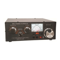
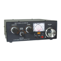
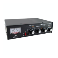
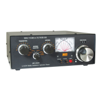
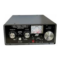
Do you have a question about the MFJ VersaTuner V MFJ-989D and is the answer not in the manual?
Dual-range power meter with cross-needle movements, LED illumination, directional coupler, and dual detectors.
Heavy-duty ceramic switch with silver-plated contacts for routing loads to various antennas.
Precision non-inductive 50-Ohm load resistor, convection cooled, rated for 300 Watts dissipation.
T-network with 500-pF capacitors and 24-uH AirCore rotary inductor for continuous HF coverage.
Guanella-style current balun with two massive ferrite cores for high-voltage applications.
Powers meter electronics; external DC is needed for meter LED lighting.
Meter Lamp power jack for 12 vdc input, uses a 2.1-mm plug for operation.
Series capacitor on Transmitter side of the T-network, offers variable capacity.
Series capacitor on the Antenna side of the T-network, offers variable capacity.
Continuously adjustable shunt inductor with a counter dial spanning 000 to 090.
Six-position switch for routing signals to different antennas or the dummy load.
Displays Forward Power on either a 300-W or 3-kW scale.
Displays Reflected Power on either a 60-W or 600-W scale.
Selects the metering circuit's power range, either x1 (Low) or x10 (High).
Selects the meter detection mode between Peak (PK) or Average (AVG).
Turns the meter's LED lighting on or off.
2.1-mm coaxial power jack accepts 12 vdc to operate LED meter lamps and metering circuit.
Accepts PL-259 connector for connecting transceiver or amplifier.
Accepts PL-259 connector, connects antenna #1 to the tuner's routing switch.
Accepts PL-259 connector, connects antenna #2 to the tuner's routing switch.
Chassis ground connection for the tuner to the station's ground system.
Antenna side of the 1:1 balun, accepts balanced feedlines.
Terminal post accepts single-wire antennas and connects to the balun.
Position for control access, avoid contact with RF-energized lines.
Use a short, direct, 50-Ohm cable rated for full power; avoid baluns in-line.
Connect tuner chassis directly to station's ground system for safety and performance.
Disconnect antennas during storms; arrestors help, but disconnection is key.
Measures CW/FM carrier and SSB voice power, distinguishing peak vs. average.
Formula (Po = FP - RP) to calculate power into a mismatched load.
Formula to calculate SWR using Forward and Reflected power meter values.
Transmit line routed directly to the Coax-1 output connector.
Transmit line routed directly to the Coax-2 output connector.
Transmit line routed directly to the internal 50-Ohm dummy load.
Transmit line routed through the T-network to the Coax-1 output.
Transmit line routed through the T-network to the Coax-2 output.
Transmit line routed through the T-network to the Wire terminal post.
Use to pre-tune transceivers or normalize PAs for 50-Ohm output before T-network.
Use to check power output up to 300 Watts via the tuner's precision wattmeter.
Wound on toroid cores, terminated to ceramic terminal posts for high-voltage handling.
Features two series capacitors and a shunt inductor, practical for amateur radio tuning.
Rule: use highest capacitance with smallest inductance for lowest loss and best power handling.
Confirm selector, handle inductor carefully, pre-tune PAs if necessary.
Use low power initially, especially with high-power amplifiers, to avoid damage.
Pre-tune PAs into a 50-Ohm load before routing through the T-network.
Alternative method for tuning that eliminates QRM to other stations.
Detailed steps for adjusting capacitors, inductor, and power for minimum SWR.
Discusses tuning range limits and potential need for antenna adjustments for matching.
Applies the 'C-high L-low' rule for Transmitter/Antenna controls and Inductor settings.
Procedure to reset the inductor counter if it slips out of calibration.
Logging settings aids future setup and quick troubleshooting of antenna site changes.
Recap of key safety points: exposed terminals, operating with cover off, hot switching.
Double-check all connections and repeat the tuning procedure.
Check connections, use minimum inductance/maximum capacitance; reduce power if arcing persists.
Keep radiating wires away from other wiring; use insulated wire for reduced RFI.
A good RF ground is essential for counterpoise, performance, and safety.
RF and lightning travel on conductor surfaces; use smooth metallic conductors.
Recommended lengths for long-wires and dipoles, emphasizing clear installation.
Discusses matching high-Z loads and the impact of feedline length on impedance.
Strategies for feeding multi-band antennas, adjusting feedline length for optimal matching.
A provided chart to log tuner settings by frequency, transmitter, inductor, and antenna.
Details on proof of purchase, repair/replacement process, and warranty limitations.
| Type | Antenna Tuner |
|---|---|
| Model | MFJ-989D |
| Antenna Selection | Manual |
| Capacitors | Air variable capacitors |
| Tuning Method | Manual |
| Metering | SWR/Power meter |
| Frequency Range | 1.8 to 30 MHz |
| Inductor Type | Roller inductor |
