Do you have a question about the MFZ Ovitor CS 300 RM and is the answer not in the manual?
Manual copyright and alteration notice.
Functionality guarantee and liability disclaimer.
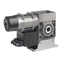
Specifies control unit's purpose for tubular drives.
Defines qualified electricians as authorized users.
Safety guidelines for power disconnection and wiring.
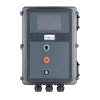
Details package options for CS 300 RM controls and housing units.
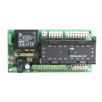
Diagram and key for the main board with LCD display monitor.
Ensures door, drive, and control unit are installed and ready.
Warnings on correct mains voltage and switch installation.
Wiring details for the motor and power supply at terminal X1.
Explains connections for command/safety devices to terminals X3, X4, X5.
Illustrates wiring for OPEN/STOP/CLOSE buttons and impulse buttons.
Diagram and key for LED module indicators (H1, H2, H3).
Describes AUTOMATIC and ADJUSTMENT modes via LED status.
Procedure to adjust mechanical limit switches in ADJUSTMENT mode.
Diagram and key for the LCD monitor interface (A-H).
Explains AUTOMATIC, ADJUSTMENT, INPUT, and DIAGNOSIS modes.
Describes display status for AUTOMATIC OPENING, CLOSING, and STANDBY.
Details functions, settings, and factory presets for input parameters.
Explains various MOD functions like REVERS, LB CLOSE, SKS LEAD.
Details MOD functions for traffic light signals in various positions.
Details MOD functions for position messages (end, pre-limit positions).
Explains MOD functions for impulse signals upon OPEN command or end position.
Details MOD functions for brake activation, negation, and during open time.
Details MOD 5 for general errors and MOD 17 for safety edge errors.
Explains MOD functions for magnetic lock, transmission, safety devices, yard light.
Details status indicators for UP-SWITCH, DOWN-SWITCH, SKS, IMPULS.
Troubleshooting for no response or reversed door movement.
Rectification for stop commands or exceeded running time.
Troubleshooting for safety edge protection (SKS) faults.
Diagram showing connections for terminal blocks X5, X10, X8, X9, X1, F1.
| Brand | MFZ Ovitor |
|---|---|
| Model | CS 300 RM |
| Category | Gate Opener |
| Language | English |