Do you have a question about the MFZ Ovitor CS 320 FU and is the answer not in the manual?
Details copyright, alterations, dimensions, and diagram scale in the manual.
Explains warning, caution, attention symbols for risk identification.
Covers product warranty, designated use, and qualifications for electricians.
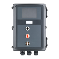
Describes the CS 320 FU's purpose and lists available housing, LCD, and command device variants.
Details the CS 320 FU motherboard, terminal strips, connectors, and status indicators.
Explains versions CS 320 FU-I (separate housing) and CS 320 FU-E (integrated housing).
Wiring diagrams for connecting Siemens G110 and V20 frequency converters.
Essential safety rules for electrical work, including disconnecting power and proper routing.
Prerequisites for mains connection, including voltage matching, rotating field, and circuit breakers.
Information on internal fuse protection (F2) and its limitations.
How to adjust the bridge connector on X21 for 230V or 400V supply.
Details on 230V-AC and 24V-DC power supplies for external components via X19 and X4.
Wiring and connection details for absolute value encoders (AWG) as limit position systems.
Guidance on connecting mechanical limit switches for door position detection.
Wiring for various command devices like UP/STOP/DOWN switches, impulse buttons, and key switches.
Instructions for connecting light grids and closing edge protective devices.
Wiring for different types of light barriers (NC, NPN, PNP, 2-wire).
Details on connecting and configuring the controller's programmable inputs.
Wiring and requirements for safety inputs using 8.2 kOhm components per EN 12453.
Information on connecting pluggable radio receivers and transmission systems.
How to connect a Siemens frequency converter for speed control.
Connecting the LCD monitor and MS BUS components for system expansion.
Details on the bi-directional radio system for safety signal transmission.
Steps to verify and correct the motor's travel direction.
How to set UP and DOWN limit positions using mechanical switches.
Setting UP/DOWN end positions using buttons on the circuit board.
Setting UP/DOWN end positions via the LCD monitor interface.
Setting intermediate door positions using the LCD monitor.
Explanation of the LCD display, buttons, operating modes (AUTOMATIC, ADJUSTMENT, INPUT, DIAGNOSIS).
Accessing the expert menu and performing controller resets to factory settings.
Step-by-step guide to resetting the controller using the LCD monitor.
Procedure for resetting the controller using circuit board buttons.
How to reset frequency inverter parameters to factory defaults.
How the frequency converter controls door speed and benefits.
List of parameters for adjusting speed, acceleration, and deceleration times.
Visual representations of door movement patterns under various conditions.
Setting motor parameters like voltage, current, and frequency to match the type plate.
Explains display messages and states in AUTOMATIC mode (OPENING, CLOSING, STANDBY, STOP).
Describes system states in MANUAL mode, typically activated by "Self-locking" parameter.
Details functions and parameters configurable via the input operating mode.
Explains functions assigned to relays based on MOD numbers for traffic lights, position messages, etc.
How relay modes control traffic light signals based on door position and parameters.
How relay modes indicate door limit and intermediate positions.
Descriptions of pulse signals generated by specific relay modes for external actuation.
How relay mode 4 controls brake functions (closed/open circuit principle).
How relay actions correspond to system error messages.
Messages related to input status (e.g., battery operation, fire alarm) and their remarks.
System messages for service intervals or operating mode changes.
Detailed explanation of functions assignable to Input 1 for various controls.
Detailed explanation of functions assignable to Input 2, including safety switching.
How to access and interpret diagnostic data, error memory, and system status.
Lists faults, their causes, and rectification steps shown on the LCD monitor.
Explains error messages indicated by LED status lights on the main circuit board.
Further fault messages for SKS and light barriers, including deadman mode operations.
Details on housing dimensions, power supply, current ratings, fuse protection, and operating conditions.
Technical data on safety function categories and performance levels per EN ISO 13849-1.
Diagram showing specific points for measuring safety circuit voltage to locate interruptions.
A comprehensive wiring diagram illustrating all external connections to the CS 320 FU controller.
| Brand | MFZ Ovitor |
|---|---|
| Model | CS 320 FU |
| Category | Controller |
| Language | English |