CHECKING
1) Terminal wiring: Check that all cables are correctly con-
nected according to the connection diagram.
2) Power input voltage: Check voltage across the terminal
7 – 8 with a multimeter.
3) Input: Check that the input signal is within 0 – 100% of
the full-scale.
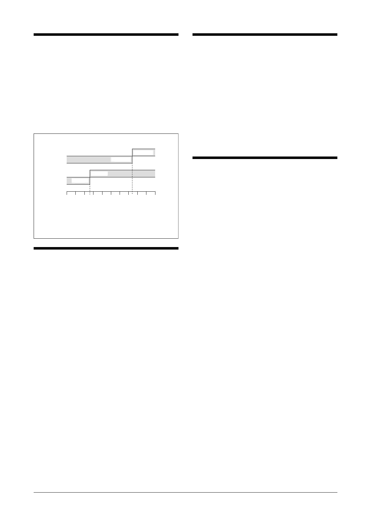
4) Alarm operations: Check the alarm operations referring
to the figure below.
5) Output load: Check that the output load is 380V
AC/120VA or 125V DC/30W at the maximum. For use
with inductive load, external protection is recommended.
Output Code: 1 & 4
: Terminals 1 – 2, 9 – 10 turn ON
Alarm Trip Operation Terminal No. in parentheses
Trip Operation in Power Failure
•
• Output Code: 2 & 3
: Terminals 1 – 3, 9 – 11 turn ON
050 100▲
Input
(%)
Output 2
Setpoint
▲
Output 1
Setpoint
Output 1
(9-10)ON
Output 2
(1-2)ON
(1-3)ON
(9-11)ON
ADJUSTMENT PROCEDURE
■ ALARM SETPOINT AND DEADBAND (HYSTERESIS)
1) Apply a simulated input signal appropriate for alarm set-
point.
2) For a Hi setpoint, turn the setpoint adj. from 100% (from
0% for Lo) until the relay trips.
3) Decrease (increase for Lo) the input signal by desired
deadband (hysteresis) width.
4) Turn the deadband (hysteresis) adj. from 100% until the
relay trip is cancelled.
MAINTENANCE
Regular calibration procedure is explained below:
■ CALIBRATION
Warm up the unit for at least 10 minutes.
• Hi Setpoint
Increase the input signal from a value lower than the set-
point and check that the trip point remains within the
accuracy described in the data sheet.
• Lo Setpoint
Decrease the input signal from a value higher than the
setpoint and check that the trip point remains within the
accuracy described in the data sheet.
When the trip points are shifted, please contact our sales
office or representatives.
LIGHTNING SURGE PROTECTION
We offer a series of lightning surge protector for protec-
tion against induced lightning surges. Please contact us to
choose appropriate models.
ACV
EM-2117 Rev.9 P. 3 / 3
MG CO., LTD. www.mgco.jp
5-2-55 Minamitsumori, Nishinari-ku, Osaka 557-0063 JAPAN
 Loading...