MS
EM-1651 Rev.8 P. 2 / 2
MG CO., LTD. www.mgco.jp
5-2-55 Minamitsumori, Nishinari-ku, Osaka 557-0063 JAPAN
■ OPTION /E: LCD METER
Front Cover (open)
Setpoint Adj.
LCD Meter
• LCD Meter
Output value is displayed in 0 to 100%.
• Setpoint adjustment
Adjust the setpoint while checking a value displayed on the
LCD meter.
Default setting: 0%
INSTALLATION
Detach the yellow clamps located at the top and bottom of
the unit for separate the body from the base socket.
Clamp
(top & bottom)
DIN Rail
35mm wide
Spring Loaded
DIN Rail Adaptor
Shape and size of the base socket
are slightly different with various
socket types.
■ DIN RAIL MOUNTING
Set the base socket so that its
DIN rail adaptor is at the bot-
tom. Hang the upper hook at
the rear side of base socket on
the DIN rail and push in the
lower. When removing the
socket, push down the DIN
rail adaptor utilizing a minus
screwdriver and pull.
■ WALL MOUNTING
Refer to “EXTERNAL DI-
MENSIONS.”
TERMINAL CONNECTIONS
Connect the unit as in the diagram below or refer to the connection diagram on the top of the unit.
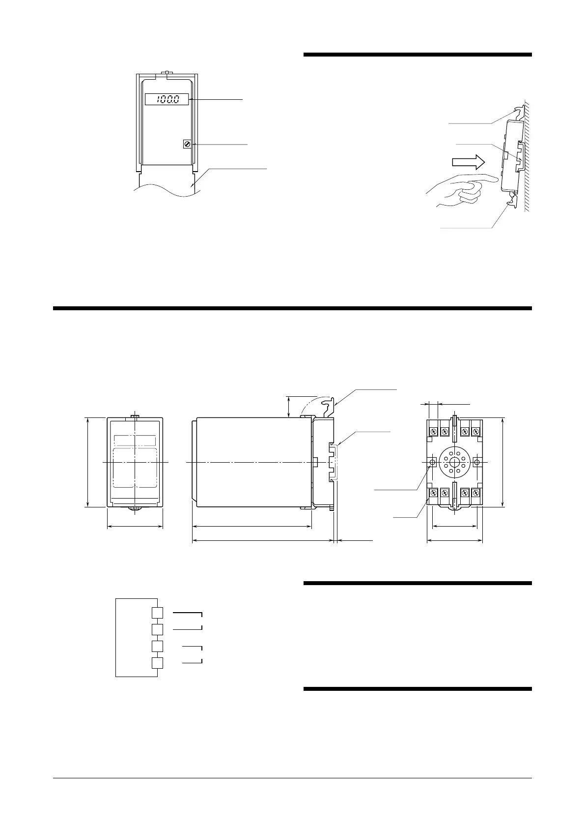
■ EXTERNAL DIMENSIONS unit: mm (inch)
3456
2187
80 (3.15)
50 (1.97) 107 (4.21)
127 (5) [3.3 (.13)]
80 (3.15)
20
(.79)
40 (1.57)
50 (1.97)
7.8 (.31)
CLAMP
(top & bottom)
DIN RAIL
35mm wide
2–4.5 (.18) dia.
MTG HOLE
15 (.59) deep
8–M3.5
SCREW
• When mounting, no extra space is needed between units.
■ CONNECTION DIAGRAM
+
–
OUTPUT
1
2
U(+)
V(–)
POWER
7
8
CHECKING
1) Terminal wiring: Check that all cables are correctly con-
nected according to the connection diagram.
2) Power input voltage: Check voltage across the terminal
7 – 8 with a multimeter.
3) Output: Check that the load resistance meets the de-
scribed specifications.
LIGHTNING SURGE PROTECTION
We offer a series of lightning surge protector for protec-
tion against induced lightning surges. Please contact us to
choose appropriate models.
 Loading...