~~~~~----------,-----------THE
BODY R
The
rear
wings may be left In position
but
it is
advisable
to
remove
them
as detailed in Section R.6
to
prevent
damage.
Remove
the
bolts and
spring
and plain
washers
securing
the
rear
bumper
to
the
chassis frame and
withd
raw
the
bu m
per
bar
assern bly and distance
tu
bes.
Remove
the
spare
wheel
and
extract
the
bolts
and
two
Phillips
screws
with
spring
and flat
washers
to
release
the
rear
valance.
Drain
the
fuel
tank,
disconnect
the
delivery pipe
and fuel gauge
tank
attachment
cable.
Slacken
the
nut
and
locknut
on
the
lower
end
of
each fuel
tank
strap
and
the
bolts clamping
the
spare
wheel
carrier
to
the
chassis frame
rear
cross-tube.
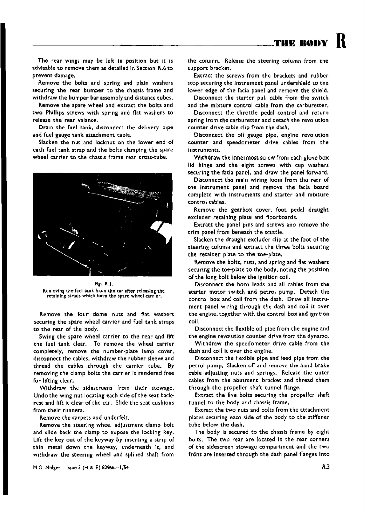
fig. R.1.
Removing the fuel
tank
from
the
car
after
releasing
the
retaining
straps
which form
the
sparewheel
carrier.
Remove
the
four
dome
nuts and flat washers
securing
the
spare
wheel
carrier
and fuel
tank
straps
to
the
rear
of
the
body.
Swing
the
spare
wheel
carrier
to
the
rear
and
11ft
the
fuel
tank
dear.
To
remove
the
wheel
carrier
completely,
remove
the
number-plate
lamp cover,
disconnect
the
cables,
withdraw
the
rubber
sleeve and
thread
the
cables
through
the
carrier
tube.
By
removing
the
clamp bolts
the
carrier
is
rendered
free
for lifting
dear.
Withdraw
the
sidescreens
from
their
stowage.
Undo
the
wing
nut
locating each side
of
the
seat
back-
rest
and lift it
clear
of
the
car. Slide
the
seat
cushions
from
their
runners.
Remove
the
carpets
and underfelt.
Remove
the
steering
wheel
adjustment
damp
bolt
and slide back
the
damp
to
expose
the
locking key.
Lift
the
key
out
of
the
keyway by
inserting
a
strip
of
thin
metal
down
the
keyway,
underneath
It. and
withdraw
the
steering
wheel
and splined shaft from
M.G.
Midget.
Issue
3 (H & E) 82966--1/54
the
column.
Release
the
steering
column from
the
support
bracket.
Extract
the
screws
from
the
brackets
and
rubber
stop
securing
the
instrument
panel undershleld
to
the
lower
edge
of
the
facia panel and
remove
the
shield.
Disconnect
the
starter
pull cable from
the
switch
and
the
mixture
control
cable from
the
carburetter,
Disconnect
the
throttle
pedal
control
and
return
spring
from
the
carburetter
and
detach
the
revolution
counter
drive
cable clip
from
the
dash.
Disconnect
the
oil gauge pipe.
engine
revolution
counter
and
speedometer
drive
cables
from
the
i
nstru
rnents,
Withdraw
the
Innermost
screw
from each glove
box
lid hinge and
the
eight
screws
with
cup
washers
securing
the
facia panel, and
draw
the
panel
forward.
Disconnect
the
main
wiring
100m
from
the
rear
of
the
instrument
panel and
remove
the
facia
board
complete
with
Instruments
and
starter
and
mixture
control
cables.
Remove
the
gearbox
cover,
foot
pedal
draught
excluder
retaining
plate
and floorboards.
Extract
the
panel pins and screws
and
remove
the
trim
panel from
beneath
the
scuttle.
Slacken
the
draught
excluder
clip at
the
foot
of
the
steering
column and
extract
the
three
bolts
securlng
the
retainer
plate
to
the
toe-plate,
Remove
the
bolts,
nuts,
and spring and flat washers
securing
the
toe-plate
to
the
body, noting
the
position
of
the
long
bolt
below
the
ignition coil.
Disconnect
the
horn
leads and all cables
from
the
starter
motor
switch
and
petrol
pump. Detach
the
control
box
and coil
from
the
dash.
Draw
all
instru-
ment
panel
wiring
through
the
dash and coil it
over
the
engine,
together
with
the
control
box
and
Ignition
coil.
Disconnect
the
flexible oil pipe from
the
engine and
the
engine
revolution
counter
drive
from
the
dynamo.
Withdraw
the
speedometer
drive
cable
from
the
dash and call it
over
the
engine.
Disconnect
the
flexible pipe and feed pipe
from
the
petrol
pump.
Slacken
off
and
remove
the
hand
brake
cable adjusting nuts and springs. Release
the
outer
cables from
the
abutment
bracket
and
thread
them
through
the
propeller
shaft
tunnel
flange.
Extract
the
five bolts sec uri ng
the
propeller
shaft
tunnel
to
the
body and chassis frame.
Extract
the
two
nuts and bolts from
the
attachment
plates securing each
side
of
the
body
to
the
stiffener
tube
below
the
dash.
The
body Is
secured
to
the
chassis
frame
by
eight
bolts.
The
two
rear
are
located In
the
rear
corners
of
the
sldescreen
stowage
compartment
and
the
two
front
are
inserted
through
the
dash panel flanges
into
R.3
Wishvilles Classic
Automobile Library
 Loading...