This document is a repair manual for ROTAC® Models SB-18 and SB-18.2 actuators, manufactured by BROMMA and distributed by Micromatic LLC. It provides comprehensive instructions for disassembly, evaluation, correction, preparation, seal installation, and assembly, with or without specialized tools. The manual also includes reference information and specifications crucial for proper maintenance and repair.
Function Description
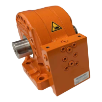
The ROTAC® SB-18 and SB-18.2 models are rotary actuators, hydraulic devices designed to produce oscillating rotary motion. They are used in various applications requiring precise angular positioning and torque. The manual distinguishes between two generations of these actuators:
- 1st Generation (GEN1) SB-18: Models 26-10-7707 (BR1002277) and 26-10-7712 (BR1001276).
- 2nd Generation (GEN2) SB-18.2: Models 26-10-7747 (BR1709884) and 26-10-7748 (BR1709888).
GEN2 actuators are identifiable by a ".2" milled into the side face under the shaft and lower left corner of the manifold.
Important Technical Specifications
The manual provides critical dimensions and torque specifications for maintaining actuator performance and longevity.
Head and Shaft Journal Diameters:
These dimensions are crucial for proper actuator function.
- SB-18 (GEN1):
- Head Journal: Maximum Ø 2.7776 in. (70.5510 mm), Minimum Ø 2.7766 in. (70.5256 mm).
- Shaft Journal: Maximum Ø 2.7732 in. (70.4393 mm), Minimum Ø 2.7730 in. (70.4342 mm).
- SB-18.2 (GEN2):
- Head Journal: Maximum Ø 2.7761 in. (70.5129 mm), Minimum Ø 2.7766 in. (70.4875 mm).
- Shaft Journal: Maximum Ø 2.7732 in. (70.4393 mm), Minimum Ø 2.7730 in. (70.4342 mm).
Torque Specifications:
Proper torquing is essential to prevent internal bypass and ensure actuator performance.
- 1/2-13 Head Bolts:
- SB-18 (GEN1) & SB-18.2 (GEN2): 115 ft·lbf (156 N·m). Medium strength thread lock (Lock-Tite 242, Perma-Lock # HM128 or equivalent) is required.
- CPR Cartridge:
- SB-18 (GEN1) & SB-18.2 (GEN2): 45-50 ft·lbf (61-88 N·m). No thread lock is to be used on CPR Cartridge.
Breakaway and Bypass Specifications:
These indicate the actuator's efficiency and internal leakage.
- SB-18 (GEN1):
- Breakaway Pressure: 100 psi (7 bar).
- Internal By-Pass / Leak: 10 in³ / minute @ 3,000 psi (164 cm³ / minute @ 207 bar).
- SB-18.2 (GEN2):
- Breakaway Pressure: 100 psi (7 bar).
- Internal By-Pass / Leak: 10 in³ / minute @ 3,000 psi (164 cm³ / minute @ 207 bar).
Note: All vane type actuators should exhibit zero internal bypass/leak.
Seal Kits:
Specific seal kits are available for each generation.
- SB-18 (GEN1):
- All Seals: 26-90-7707
- Shaft Seals Only: 26-90-7707-1
- SB-18.2 (GEN2):
- All Seals: 26-90-7747
- Shaft Seals Only: 26-90-7747-1
Usage Features
The manual highlights several key features related to the design and interchangeability of components:
- Shaft Types: Both generations can have flat or round end shafts.
- Heads: GEN2 heads can be serviced by removing and replacing the journal bearing and final machining. GEN1 heads require replacement if out of specification.
- Shaft Seals: GEN2 has new material and quantities of seals used. GEN2 seals are NOT interchangeable with GEN1 heads.
- Shoulder Seal: Additional wavy spring energizers are used per side for GEN2 actuators (two per side) compared to GEN1 (one per side). GEN2 wavy springs and quantity are IS interchangeable with GEN1 heads and assemblies.
- Pressure Relief Cartridge: GEN2 cartridges are NOT interchangeable with GEN1 manifolds. Pressure relief cartridges are pre-set from the factory and should NOT be adjusted.
- Manifold: GEN2 manifolds are IS interchangeable with GEN1 manifolds.
- External Shims: GEN2 does NOT have external shim discs, but it is acceptable to install them. GEN1 shim discs CAN BE installed on GEN2 actuators if desired.
- Bearing Pads: GEN2 actuators use two (2) bearing pads per side, while GEN1 actuators do not have bearing pads. External disc shims are installed on the outside of the assembly for GEN1.
Maintenance Features
The manual provides detailed instructions for maintaining the actuators, emphasizing precision and care to ensure optimal performance and longevity.
Disassembly:
- Preparation: A clean workbench and proper tools are essential. Exploded views in Section 7 aid in identifying parts.
- Cleanliness: Thorough cleaning of the assembly area and external unit is crucial to prevent contamination.
- Marking Parts: Mark the body, heads, and shaft to ensure correct reassembly.
- Shaft Removal: Address dings and burrs before removal. Pull the shaft out carefully to avoid damage to the body, journals, or 'A' diameter. Remove all seals and inspect for damage.
- Manifold Removal: Remove SHCS bolts and O-rings.
- Head Removal: DO NOT PRY HEADS OFF. Use jack screws to separate heads from the body. An air hammer is recommended for dowel removal.
Evaluation and Corrections:
- Oil Residue: Examine for clues about damage. Contaminated oil causes scoring. Varnish indicates overheating. Metallic particles suggest wear in hydraulic components.
- Cleaning: Wash all parts thoroughly.
- Shaft Inspection: Clean thoroughly. Examine critical areas for cracks (vane, keyways, 'A' diameter). Use Magnaflux for crack detection. Polish rust from outer seal edges radially with 600 grit or higher paper/pad.
- Body Inspection: Check for scoring, dings, burrs, and journal diameter. Ensure shoe seal grooves are smooth.
- Heads Inspection: Repair scoring on the face. Measure journal diameter and refer to Section 7 for specifications. Clean seal glands and ensure burr-free edges.
- Seals: ALWAYS replace all seals. Do NOT reuse seals. Refer to Seal Kits Table in Section 7.
Preparation and Seal Installation:
- General: Ensure all parts are clean, burr-free, and smooth.
- Vane Seal Installation: Install rubber vane seal energizer and vane seal cap. Use wooden handle to press 'Earmuff' into pocket.
- Shaft Seal Installation: Install back-up ring and O-ring into the head (GEN1) or O-ring and seal cap (GEN2). Use assembly grease to aid installation.
- Shoulder Seal Installation: Place wavy springs and hub seal ring into the head pocket. Install shoulder seal, ensuring a tight diametrical fit.
- Head Seal Installation: Place head seal (O-ring) into the head seal groove using assembly grease.
Assembly with Assembly Tools:
- Tool Kits: Two different assembly kits are available for flat and round shaft ends (26-97-0348 and 26-97-0349).
- Dummy Head (SK-4312), "Dummy Dowels" (A010152), Bolts (26-12-0141): Use these tools to align and secure the head during assembly.
- Shoe Seal Protector (SK-5238-02): Prevents damage to the shoe seal during installation.
- Vane Seal Protector Tool (SK-4318): Protects the vane seal during assembly.
- Shaft Installation: Position the shaft correctly (hole orientation for flat shafts, slots for round shafts).
- Bearing Pad Installation: Install bearing pads for GEN2 actuators.
- Head Installation: Use Shaft Seal Protector Tool (SK-4391 for flat, SK-3229 for round) and Dummy Key Tool (SK-4399 for round shafts). Lower the head slowly to avoid dislodging seals.
- Head Dowels and Bolts Installation: Install dummy dowels, then head bolts (snug only, not fully torqued initially).
- Pressure Relief Cartridge: Install and torque according to specifications. Do NOT force.
- Manifold Installation: Install O-rings and manifold bolts, torquing in an alternating pattern.
- External Disc / Arm Shim Installation: Slip shims around the shaft end (GEN1 only, optional for GEN2).
Assembly Without Assembly Tools:
- Support Blocks: Fabricate wooden support blocks to aid assembly.
- Body Orientation: Orient the body with the vane indicator forward.
- Shoe Seal Install: Install shoe seal and cushion using assembly grease.
- Shaft Install: Orient the shaft end features as shown. Lower the shaft into the body carefully.
- Bearing Pad Installation: Install bearing pads for GEN2 actuators.
- Head Install (pre-assembled): Carefully lower the head over the shaft, ensuring seals are not dislodged.
- Reposition Assembly for 2nd Head Installation: Hold the shaft firmly against the head surface to prevent seal damage.
- Bearing Pad Installation #2: Install bearing pads for the second head.
- Head Installation #2: Slide the second head onto the body.
- Dowels and Head Bolts Installation: Install dowel pins (freezing them can ease installation) and remaining head bolts, torquing all bolts to specification.
- Manifold Installation: Install O-rings and manifold bolts, torquing to specification.
- External Disc / Arm Shim Installation: Slip shims around the shaft end.
Troubleshooting:
The manual includes a comprehensive troubleshooting guide, linking common issues (e.g., external leaks, internal bypass) to possible causes and recommended remedies. This includes inspecting seals, checking for contamination, repairing damaged surfaces, verifying torque, and replacing defective parts. For example, excessive internal bypass could be due to defective internal seals, a pinched hub seal, or compressed wavy springs, with remedies ranging from seal replacement to inspecting bearing pads.