Do you have a question about the Microscan MicroHAWK MV-20 and is the answer not in the manual?
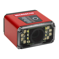
The MicroHAWK MV-20, MV-30, and MV-40 are advanced machine vision cameras designed for a wide range of industrial applications, from basic auto-ID to complex machine vision tasks. These devices are engineered to simplify setup and operation, making them accessible for both experienced users and those new to machine vision.
The primary function of the MicroHAWK MV series is to capture images and perform various machine vision inspections. This includes decoding 1D and 2D barcodes, optical character recognition (OCR), measuring distances, counting objects, and verifying product features. The cameras integrate seamlessly with the AutoVISION software, which provides a user-friendly interface for configuring and running inspection jobs.
The MV series cameras are capable of capturing high-resolution images, which are then processed by the AutoVISION software to extract relevant information. For instance, in an auto-ID application, the camera captures an image of a barcode, and the software decodes the information embedded within it. In a measurement application, the software analyzes the captured image to determine distances or dimensions of an object. For OCR, the camera reads text printed on a surface, converting it into digital data.
The cameras support various lighting modes and can be adjusted for exposure, gain, and focus to optimize image quality for different environments and object types. This adaptability ensures reliable performance across diverse industrial settings, from well-lit production lines to challenging low-light conditions.
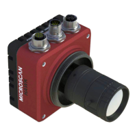
The MicroHAWK MV series is designed for ease of use, starting with its straightforward hardware connection. The MV-20 and MV-30 models primarily use USB connections for both power and data, simplifying integration with host PCs. The MV-40 model offers Ethernet connectivity, providing more robust networking capabilities for industrial environments. For USB connections, the system automatically configures the PC address, while for Ethernet, users may need to manually set the PC's IP range to match the camera's default IP address.
The AutoVISION software guides users through the entire setup process, from connecting the device to creating and running inspection jobs. Upon launching AutoVISION, users can select their camera from a dropdown menu and choose to create a new job, load an existing one, or upload a job from the camera. The software's intuitive interface allows users to evaluate captured images, auto-calibrate camera parameters, and adjust settings like exposure, gain, and focus. The "Auto Calibration" feature automatically optimizes camera parameters for the best image capture, reducing manual configuration effort.
Creating an inspection job involves dragging and dropping various tools onto the image area. For example, to decode a barcode, users can drag the "Decode Tool" onto the image and define a region of interest around the barcode. Similarly, "OCR Tool" can be used for text recognition, "Measure Tool" for dimensional checks, and "Count Tool" for counting objects. The software provides visual feedback, allowing users to see the results of their tool configurations in real-time.
The "Edit view" in AutoVISION offers a comprehensive workspace where users can set camera parameters, add machine vision tools, configure tool parameters, and define I/O inspection outputs. The ability to adjust lighting modes, trigger types, and trigger polarity further enhances the camera's versatility, allowing it to adapt to specific application requirements. For instance, users can choose between continuous or triggered image capture, and set up external triggers for precise timing.
The software also includes features for testing jobs. Users can "Try Out Job Once" to test a single image capture or "Try Out Job in Loop" to continuously test the job on multiple images, which is particularly useful for fine-tuning parameters and ensuring consistent performance. Once a job is configured and tested, it can be downloaded to the camera and run, with inspection results and active tools displayed in the interface.
While the MicroHAWK MV series cameras are designed for robust industrial use, certain aspects contribute to their long-term maintenance and reliability. Proper mounting and positioning are crucial for optimal performance. Users are advised to position the camera at a suitable focal distance and tip it to avoid glare from direct reflection. Ensuring the case parting line is perpendicular to the symbol's plane helps minimize skew and pitch, which can affect reading accuracy.
Lighting is a critical factor for machine vision applications. The cameras are designed to work with various lighting conditions, and users may need to add external lighting from Microscan's NERLITE family to maximize contrast and minimize interference. Considerations such as object surface texture (flat, bumpy, matte, shiny), object shape (curved, flat), color, and movement (moving or stationary) all influence the choice and configuration of lighting.
The cameras are built with durable enclosures, with different IP ratings (IP40 for MV-20, IP54 for MV-30, and IP65 for MV-40) indicating varying levels of protection against dust and water ingress. This ensures reliability in harsh industrial environments. For the MV-30 and MV-40 models, Microscan offers an Isolation Mounting Kit to eliminate ground loops or other external electrical noise, which is important for maintaining signal integrity and preventing damage in electrically noisy environments.
Software updates and field upgrades are also part of the maintenance strategy. While optics and illumination are factory-set for optimal alignment, LED balancing, and sealing, the camera's software is field-upgradeable via licenses. This allows users to keep their cameras updated with the latest features and improvements without needing to send the hardware back to the manufacturer. The AutoVISION software itself is regularly updated, and users can download the latest versions from the Microscan Download Center, ensuring access to the most current tools and functionalities.
| Sensor Type | CMOS |
|---|---|
| Resolution | 1280 x 1024 |
| Frame Rate | 60 fps |
| Lens Mount | CS-Mount |
| Communication | Ethernet |
| IP Rating | IP65 |
| Interface | Gigabit Ethernet |
| Light Source | Integrated LED |
| Operating Temperature | 0 to 50 °C |
| Field of View | Configurable via lens selection |
| Dimensions | 50 x 50 x 50 mm |