1 2
3
4 5
6
7
8 9 10
11
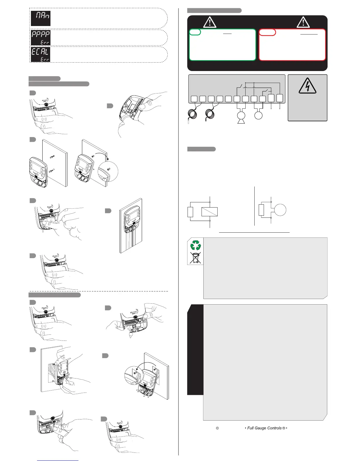
POWER
SUPPLY
SENSOR T1
METAL TIP
(COLLECTORS)
SENSOR T2
PLASTIC TIP
(POOL)
FILTER
115 Vac
or
230 Vac
0
Power supply
NOTE: check supply as product model
PUMP
FILTERPUMP
Turn off the network
before removing
the protection cover
9. IMPORTANT
According to the chapters of norm IEC 60364:
1: Install protector against overvoltage on the power supply.
2: Sensor cables and signal cables of the computer may be joined, but not in the same
electric conduit through which the electric input and the activation of the loads run.
3: Install transient suppresors (RC filters) parallel to the loads as to increase the product
life of the relays.
Contact suppressor connection diagram
Suppressor
A1
A2
A1 and A2 are the
contactor coils.
Diagram for suppressor installation for direct
drive load inputs
Load
Suppressor
For direct activation the maximum
specified current should be taken
into consideration.
Suppressors on offer from Full Gauge Controls
A qualified technician must perform
the installation of the device.
DO
DON’Ts
The controller MUST be installed:
- indoors, in a dry environment;
- away from electromagnetic fields;
- in a ventilated place, free from flammable
liquids and gases;
- protected by a circuit breaker of appropriate
specification for the installed load.
The controller MUST NOT be
installed:
- in wet places;
- exposed to sunlight or rain;
- in saunas, machine rooms or
bathrooms.
s
Failure to not comply the warnings will cause loss of warranty, equipment and / or
physical damage.
8.3 ELECTRICAL CONNECTIONS
8. INSTALLATION
8.1 SUPERIMPOSED INSTALLATION
Push the bottom openings
necessary for the passage
of cables;
Attach the controller to the wall using the
screws and plugs provided;
Make the electrical
connections of the
controller;
For a better finish
install X system
type channels to
run cables;
Place the protective cover of the
electrical connections and secure
it with the screw (included in
package).
8.2 INSTALLATION OF 4x2 BOX
The top screw must not be screwed
completely, for engaging the
controller. After fitting the controller
on the top screw, secure it with the
lower screw;
Push the rear openings
necessary for the
passage of cables;
Route the cables through the openings as
controller connections;
Secure the controller
in 4x2 box using the
screws provided;
Place the
protective cover
of the electrical
connections
and secure it
with the screw
(included in
package).
Make the electrical
connections of the controller;
The top screw must
not be screwed
completely, for
engaging the controller. After
fitting the controller on the top screw,
secure it with the lower screw;
Remove the
protective cover of
the connections at
the bottom of the
controller;
Remove the protective
cover of the connections
at the bottom of the
controller;
1
2
3
4
5
6
1
2
3
4
5
6
ENVIRONMENTAL INFORMATION
Packaging:
The materials used in the packaging of Full Gauge products are 100% recyclable. Try to
perform disposal through specialized recyclers.
Product:
The components used in Full Gauge controllers can be recycled and reused if
disassembled by specialized companies.
Disposal:
Do not incinerate or dispose the controllers that have reached the end of their service as
household garbage. Observe the laws in your area regarding disposal of electronic
waste. If in doubt, please contact Full Gauge Controls.
WARRANTY - FULL GAUGE CONTROLS
Products manufactured by Full Gauge Controls, as of May 2005, have a two (02)
yearwarranty, as of the date of the consigned sale, as stated on the invoice. They are
guaranteed against manufacturing defects that make them unsuitable or inadequate for their
intended use.
EXCEPTIONS TO WARRANTY
The Warranty does not cover expenses incurred for freight and/or insurance when sending
products with signs of defect or faulty functioning to an authorized provider of technical
support services. The following events are not covered either: natural wear and tear of parts;
external damage caused by falls or inadequate packaging of products.
LOSS OF WARRANTY
Products will automatically lose its warranty in the following cases:
- The instructions for assembly and use found in the technical description and installation
procedures in Standard IEC60364 are not obeyed;
- The product is submitted to conditions beyond the limits specified in its technical
description;
- The product is violated or repaired by any person not a member of the technical team of
Full Gauge Controls;
- Damage has been caused by a fall, blow and/or impact, infiltration of water, overload
and/or atmospheric discharge.
USE OF WARRANTY
To make use of the warranty, customers must send the properly packaged product to Full
Gauge Controls together with the invoice or receipt for the corresponding purchase. As
much information as possible in relation to the issue detected must be sent to facilitate
analysis, testing and execution of the service.
These procedures and any maintenance of the product may only be provided by Full
Gauge Controls Technical Support services in the company's headquarters at Rua Júlio de
Castilhos, 250 - CEP 92120-030 - Canoas - Rio Grande do Sul – Brasil
Rev. 03
Copyright 2013
All rights reserved.
Note: The length of the sensor cable can be increased by the user up to 200 meters using PP 2 x 24
AWG cable.
The sensor with metal tip must be installed in the solar collector, it supports a temperature of 200 º C.
- Corrective measures: Adjust parameter value F10 - Filtering manual
override time
Note: In the occurrence of any error information the controller signals the user, flashing the
display's backlight shortly, in order to grab attention.
- C orrective measures: Contact the technician responsible for
installation.
- C orrective measures: Contact the technician responsible for
installation.
- Motive: Filtering manual override with setting of parameter
[,F10]=[,,no].

 Loading...