Do you have a question about the Micsig CP2100A and is the answer not in the manual?
Essential safety precautions for using the current probes, including circuit limitations and environmental considerations.
Overview of the CP2100 series probes, their capabilities, and typical usage fields like motor drives and power supplies.
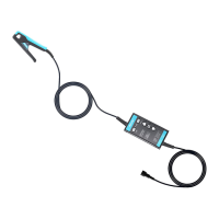
Diagram and identification of key components and connectors on the CP2100 current probe.
Detailed technical specifications including bandwidth, accuracy, ranges, and physical dimensions for CP2100A/B.
Graph illustrating the maximum current capacity of the probe as a function of measurement frequency.
Amplitude-frequency characteristic curve for the CP2100A model, showing its response across frequencies.
Amplitude-frequency characteristic curve for the CP2100B model, detailing its frequency-dependent performance.
Graph showing the DC signal linearity and uncertainty percentage relative to the measured current.
Steps for connecting the probe to an oscilloscope and configuring basic settings.
Procedure for performing zero adjustment and clamping the conductor for accurate current measurement.
Information on product warranty, recommended cleaning procedures, and handling of dirt.
Guidance on periodic checks or calibration to ensure product performance.
| Bandwidth | 100MHz |
|---|---|
| Sample Rate | 1GSa/s |
| Input Channels | 2 |
| Attenuation Ratio | 1X, 10X |
| Input Coupling | DC, AC, GND |
| Display | TFT LCD |
| Input Resistance | 1 MΩ |
| Maximum Input Voltage | 400 V (DC + AC peak) |
| Power Supply | 100V - 240V AC, 50/60Hz |
| Vertical Resolution | 8 bit |
| Timebase Range | 5ns/div ~ 50s/div |
| Trigger Types | Edge, Pulse, Video |
| Display Type | TFT LCD |
| Operating Temperature | 0°C to +50°C |
| Storage Temperature | -20°C to +60°C |
| Input Impedance | 1 MΩ ± 2% || ≤ 15 pF |