M thermal Split
202004 89
Notes:
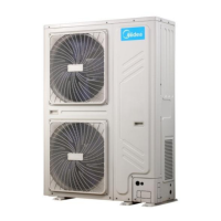
1. If the fan motor is running and the DC voltage between terminals P and N on inverter module declined, Relay on the main control board of outdoor unit is
open.
2. When replacing an inverter module, a layer of thermally conductive silica gel should be painted on IPM module (on the reverse side of the inverter module
PCB). Refer to Figure 4-4.2.
main PCB for refrigerant system
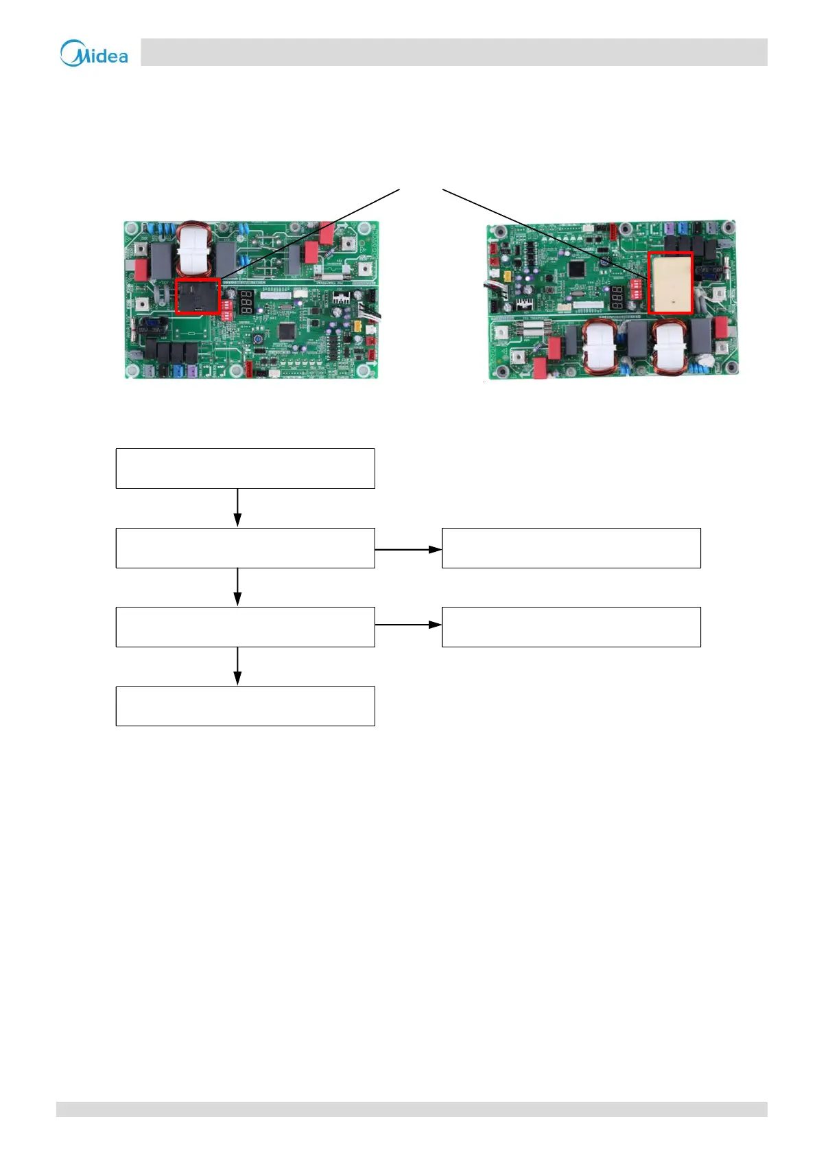
L5/L8/L9 troubleshooting 4.20.8
L5/L8/L9
The wire is not connected properly
NO
Ensure wire is connected properly
Yes
Inverter module PCB has malfunctioned
Yes
Replace inverter module PCB
1
No
Replace the compressor
1. When replacing an inverter module, a layer of thermally conductive silica gel should be painted on IPM module
reverse side of the inverter module PCB). Refer to Figure 4-4.2.
Midea CAC
 Loading...