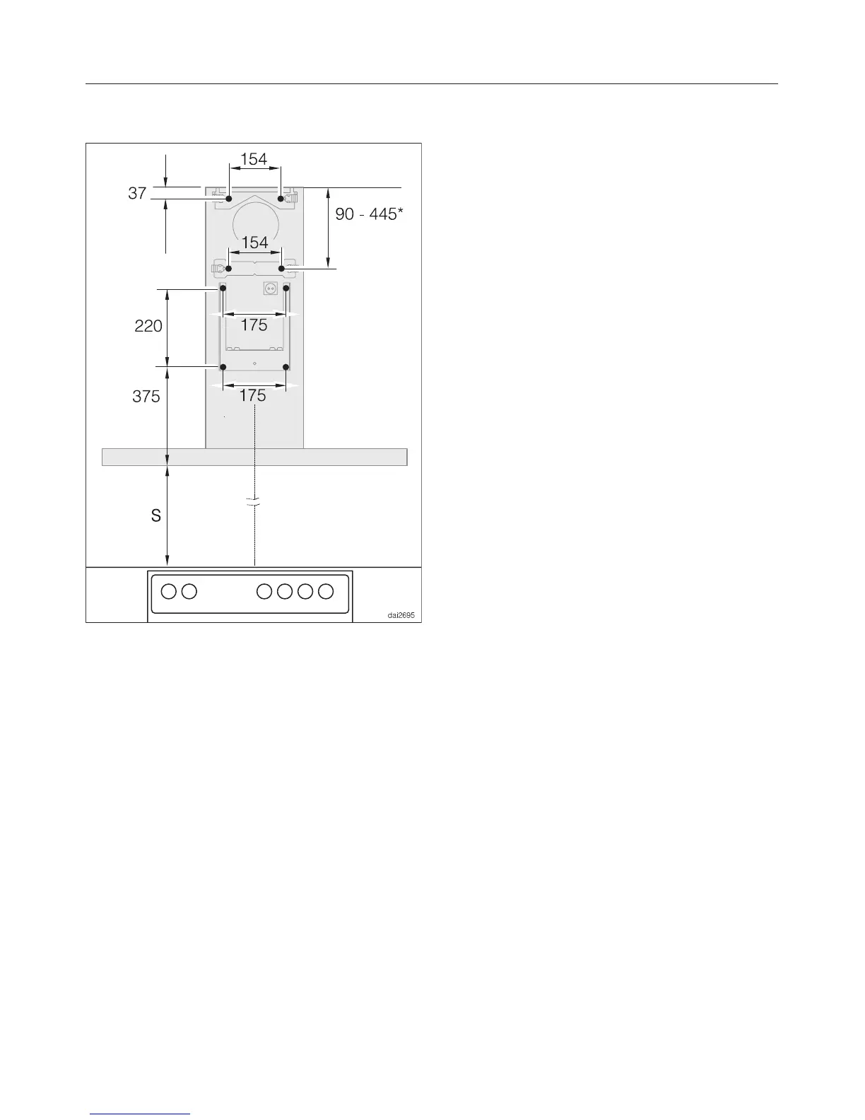
Drilling diagram
This diagram illustrates where holes for
Ø 5 mm screws need to be drilled in
the rear wall.
* The dimensions between the ceiling
and the middle bracket can vary
depending on the position of the vent
cut-out and the connection socket. It
should be installed as low as possible.
If the cooker hood is being secured
directly to the wall, please follow the
drilling instructions given in the
installation instructions supplied.
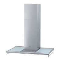
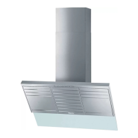
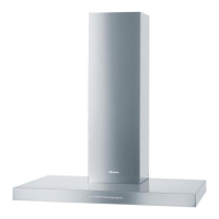
Appliance dimensions
22