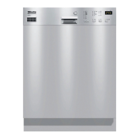
EasyManua.ls Logo

Miele G 818 User Manual

Miele G 818
138 pages
To Next Page IconTo Next Page
Page #1 background imageLoading...
Page #1 background image
TECHNICAL INFORMATION
G 600 and G 800 Dishwashers
(All US Models)
© 2011 Miele USA

Table of Contents

Other manuals for Miele G 818

Question and Answer IconNeed help?

Do you have a question about the Miele G 818 and is the answer not in the manual?

Miele G 818 Specifications

General IconGeneral
Width60 cm
Energy Efficiency ClassA
Control TypeElectronic
Salt and Rinse Aid IndicatorYes
Water ConnectionHot/Cold

Summary

1.0 Construction and Design

1.1 Appliance Overview

Provides an overview of the appliance's components and general layout.

1.2 Control Panels

Details the different types of control panels used on Miele dishwashers.

1.3 Types of Dishwashers

Describes the different dishwasher constructions: Pre-Finished, Integrated, Fully Integrated.

1.4 Technical Data

Presents technical specifications including dimensions, electrical, and plumbing.

1.5 Data Tag

Explains the location and information found on the appliance's data tag.

1.6 Layout of Components

Illustrates the component layout for Novotronic/Touchtronic and Incognito series.

2.0 Installation

3.0 Commissioning and Operation

3.1 Door Handle and Door Lock (Novotronic/Touchtronic Series)

Details the operation of the door handle and lock mechanism for specific series.

3.2 Closing the Dishwasher Door

Provides instructions on how to properly close the dishwasher door.

3.3 Child Safety Lock

Explains how to engage and disengage the child safety lock feature.

3.4 Water Softener

Covers the function, need, and setup of the water softener system.

3.5 General Operation

Outlines the general steps for operating Novotronic, Touchtronic, and Incognito models.

4.0 Description of Function

4.1 Cabinet Construction

Details the construction materials and insulation of the dishwasher cabinet.

4.2 Fan Assembly (Machines Equipped w/Turbothermic Fan)

Describes the fan assembly and its PTC release element for drying.

4.3 Combination Dispenser

Explains the construction and dispensing mechanism of the detergent and rinse aid dispenser.

4.4 Heaters

Details the two types of heating systems: cavity-style and flow-through.

4.5 Heater Circuit Operation

Illustrates the electrical circuit operation for the heater system.

4.6 Pulsed Heating – Operation

Explains the operation of pulsed heating for enhanced detergent performance.

4.7 Temperature Protection

Describes the temperature limiters and electronic protection for the heating system.

4.8 Static Drying

Explains the static drying system that uses residual heat for drying.

4.9 Spray Arms

Details the spray arms and their rotation speeds.

4.10 Filter Assembly

Describes the two-path filtration system and its components.

4.11 Water Intake – Technical Data

4.12 WaterProof System (WPS)

Explains the function and components of the WaterProof System for leak protection.

4.13 Flow Meter – Operation

Details the operation of the flow meter for measuring incoming water volume.

4.14 Water Intake

Covers water intake duration adjustments for low-pressure conditions.

4.15 Water Mixing

Explains the water mixing process, including external and integrated flow meters.

4.16 Electronically Controlled Water Hardness (EGS)

Describes the EGS system for controlling wash water hardness to prevent glass corrosion.

4.17 Water Softener

Details the water softener's components and operation, including reactivation.

4.18 Condenser Drying (UKT)

Explains the condenser drying system, its operation, and technical data.

4.19 Drain Pump, Circulation Pump

4.20 Heater Level Switch (Heater Pressure Switch)

Explains the operation of the heater level switch and its role in the heating circuit.

4.21 Level Switch (Intake Overflow)

Describes the function of the intake overflow level switch as a safety measure.

4.22 Temperature Sensor

Details the temperature sensor, its location, and resistance values at different temperatures.

4.23 Top Solo Valve

Explains the operation of the Top Solo valve for directing water to specific spray arms.

4.24 Turbidity Sensor (ECO Sensor)

Describes the turbidity sensor's function in monitoring water clarity for water saving.

4.25 Electronic – Power Outputs

Explains the role of the electronic control unit and its power output components.

5.0 Service and Maintenance

5.1 Locking Plate Adjustment

Provides instructions for adjusting the locking plate on the dishwasher door.

5.2 Door Seal Replacement

Details the procedure for removing and replacing the dishwasher door seal.

5.3 Side Panel Removal

Instructions for removing the side panels of the dishwasher for access.

5.4 Spring Bracket Replacement

Step-by-step guide for replacing the spring bracket, likely related to door tension.

5.5 Cover Plate Removal

Procedure for removing the cover plate, usually at the bottom front of the appliance.

5.6 Connecting Strip Removal

Instructions for removing the connecting strip, often found near the base.

5.7 Basket Support Roller Replacement

Guide for replacing the rollers that support the dishwasher baskets.

5.8 Removing the Combination Dispenser

Steps for removing the detergent and rinse aid dispenser assembly.

5.9 Turbothermic Fan Removal

Procedure for removing the turbothermic fan, part of the drying system.

5.10 Door Panel (Outer and Inner) Removal

Instructions for removing the outer and inner door panels of the dishwasher.

5.11 Cable Holder Removal

5.12 Lock/Handle Assembly Removal

Steps for removing the lock and handle assembly from the dishwasher door.

5.13 Door Hinge Removal

Instructions for removing the dishwasher door hinges.

5.14 Door Tension Adjustment

Guide for adjusting the door tension springs to ensure proper door operation.

5.15 Top Spray Arm Removal

Procedure for removing the top spray arm assembly.

5.16 Middle Spray Arm Removal

Instructions for removing the middle spray arm assembly.

5.17 Bottom Spray Arm Removal

Procedure for removing the bottom spray arm assembly.

5.18 Top Spray Arm Feed Pipe Removal

Steps for removing the feed pipe connected to the top spray arm.

5.19 Middle Spray Arm Cover Removal

Procedure for removing the cover for the middle spray arm.

5.20 Middle Spray Arm Feed Pipe Removal

5.21 Flow-Through Heater Removal

Procedure for removing the flow-through heater assembly.

5.22 Temperature Limiter Replacement

Steps for replacing the temperature limiter, a safety component.

5.23 Microfine Filter Replacement

Guide for replacing the microfine filter, part of the filtration system.

5.24 WaterProof System (WPS) Removal

Procedure for removing the WaterProof System (WPS) component.

5.25 WaterProof System (WPS) Restrictor Replacement

Instructions for replacing the flow restrictor within the WPS connection.

5.26 Water Inlet (Diverter) Removal

Procedure for removing the water inlet (diverter) valve.

5.27 Water Softener Operational Check

5.28 Water Softener Assembly Removal

Steps for removing the entire water softener assembly from the dishwasher.

5.29 Drip Pan Removal

Instructions for removing the drip pan, located at the base of the appliance.

5.30 Float Switch Housing Removal

Procedure for removing the housing for the float switch.

5.31 Float Switch (B8/3) Removal

Steps for removing the float switch itself from its housing.

5.32 Steam Condenser Removal

Procedure for removing the steam condenser assembly.

5.33 Control Valve (Y6) Removal

5.34 Temperature Sensor (NTC) Removal

Procedure for removing the NTC temperature sensor.

5.35 Circulation Pump (M6) Removal

Steps for removing the circulation pump (M6).

5.36 Circulation Pump Partition and Impeller Replacement

5.37 Circulation Pump Housing Replacement

Instructions for replacing the circulation pump housing.

5.38 Circulation Pump Release with Tool

Procedure for releasing the circulation pump impeller using a special tool.

5.39 Heater Pressure Switch (B1/10) Removal

Steps for removing the heater pressure switch (B1/10).

5.40 Drain Pump (M8) Removal

5.41 Top Solo Valve Removal

Instructions for removing the Top Solo valve.

5.42 Overflow Level Switch Removal

Steps for removing the overflow level switch.

5.43 Sump Removal

Procedure for removing the dishwasher sump.

5.44 Turbidity Sensor Calibration

5.45 Turbidity Sensor Removal

Instructions for removing the turbidity sensor.

5.46 Fully Integrated (Vi) Control Panel Removal

Procedure for removing the control panel on fully integrated models.

5.47 Novotronic and Touchtronic Control Panel Removal

Steps for removing the control panel on Novotronic and Touchtronic models.

5.48 Mounting Bracket Removal

Instructions for removing the mounting bracket for access to internal components.

5.49 Heater Relay and Power Relay Removal

Procedure for removing heater and power relays.

6.0 Fault Diagnosis

6.1 General Information

Overview of the three accessible modes for service purposes.

6.2 Programming and Service Mode Features

Details features available in programming and service modes.

6.3 Programming/Service Mode Access Procedures (Model Specific)

Guidance on accessing programming and service modes based on model.

6.4 Timing Charts – General Information

6.5 Wiring Diagrams – General Information

Provides general information on understanding wiring diagrams.

6.6 Timing Charts and Wiring Diagrams (Model-Specific)

References model-specific timing charts and wiring diagrams for detailed analysis.

6.7 Fault Repair

Provides troubleshooting steps and solutions for common dishwasher faults.

6.7.1 Door Does Not Close Correctly

6.7.2 Excess Foaming

Diagnosing and resolving issues related to excess foaming in the dishwasher.

6.7.3 Detergent Not Released

Troubleshooting steps when the detergent dispenser fails to release.

6.7.4 Water Leaks from the Turbothermic Fan Grille

Diagnosing and fixing water leaks originating from the turbothermic fan grille.

6.7.5 Poor Drying Results

Troubleshooting common causes for poor drying performance.

6.7.6 No Drying, or Drying Too Slow

6.7.7 Water Not Heating

Diagnosing and resolving problems where the water is not heating correctly.

6.7.8 Circulation Pump Does Not Start

Troubleshooting steps when the circulation pump fails to start.

6.8 Programming and Service Modes

6.8.1 G 841, G 841 Plus, G 842

Specific programming and service mode instructions for G 841, G 841 Plus, G 842 models.

Related product manuals