DESCRIPTION OF FUNCTIONS
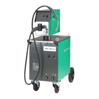
MIGMAN 385 and MIGMAN 445 are divided into the
following main modules: power source and indicator
pane.
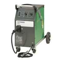
The following types of separate wire feed units can
be used:
MWF 10, MWF 11, MWF 21
Please note that it is necessary to mount af plug kit
in the power source in order to use a MWF 11 and
MWF 21 wire feed unit.
Plug kit no. 78861195 is used for welding machines
from serial number 00100138. Plug kit no. 78861196
is used for welding machines before serial number
00100138.
The wire feed units can be equipped with different
control kits if required (please see the MWF instruc-
tion manual).
Power source
The power source consists of a three-phase welding
transformer, two voltage selector switches, a rectifier
and an inductor. The power source has always
cooling with automatic stop. Approx. 4 min after the
last welding the fan stops and starts automatically
by a new welding. The fan will start running when the
internal temperature is above 60
o
C.
If the power source is equipped with a cooling unit
both this and the fan in the power source will start
running.
Indicator panel
The indicator panel indicates errors and shows
whether the machine is turned on.
Wire feed unit
The wire feed unit has always 4-roll drive system. For
many welding operations it is recommended to use
4-roll drive, especially when welding with fluxcored
wire. Furthermore, it is essential to use wire feed
rolls which correspond to the dimension of the wire
and to use torch liners of the correct diameter and
material in the welding torch (see the section
concerning Connection to MIG/MAG).
INITIAL OPERATION
Mains connection
The machine must be connected to a three-phase
mains supply and it is important to ensure that the
mains supply voltage is in accordance with the
voltage to which the machine is built. The safety
conductor (earth) is yellow/green.
The machine is equipped with a thermal cut-out
protecting against overload of the machine and
excession of max. current for the mains cable.
It is possible to select the mains fuse so the mains
cable is only protected against short-circuits. The
protection indicated on the type plate of the machine
will provide protection against both overcurrent and
short circuits.
Configuration
MIGATRONIC disclaims all responsibility for
damaged cables and other damages related to
welding with under sized welding torch and welding
cables measured by welding specifications e.g. in
relation to permissible load.
How to connect the gas
The gas hose, which is connected to the rear of the
machine, should be connected to a stabil gas
supply.
Assembly of the earth cable
The earth cable (negative pole) is fitted to the induc-
tance outlet wanted (depending on the dimension of
the welding wire). (Pos. 2-3 page 11).
How to connect the separate wire feed unit
The machine is always delivered with a MWF 10 wire
feed unit.
The plug kit for the MWF 11/21 wire feed units can
be mounted according the mounting instructions
which can be found together with the plug kit.
.
 Loading...