100 nF
20 K
1 M
B
C
D
E
F
G
H
24 VDC
+
PTC 70
100 nF
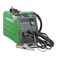
Aansluiting laskabel bij MMA
De las- en aardkabel moeten worden aangesloten op resp.
de zitting + (6) en - (5). Raadpleeg de instructies van de
electrodenleverancier bij het selecteren van polariteit.
CWF Multi (optie)
Het is mogelijk de PI via een toegewezen CAN BUS
aansluiting, die zich op de achterzijde van de machine
bevind, (optie) wel 8 CWF units aan te sluiten. Aangezien
de machine standaard niet is voorbereid om de CWF te
besturen, is het nodig om in het gebruikersmenu, het
submenu “Fdr”, te kiezen vervolgens kiezen “Act” (actieve
apparaten) en de parameter op 1 zetten.
Nu is de PI gereed om direct via de besturingsunit de CWF
te besturen: Voor ieder TIG lasprogramma is het mogelijk
de CWF unit aan te sturen en het gekoppelde CWF
draadprogramma in de range van 1 tot 20 te selecteren.
Lassen wordt gestopt en de foutcode “Fdr” wordt in het
display van de PI getoond wanneer de CWF unit in UIT-stand
staat. Dit om de gebruiker te informeren dat de CWF niet
reageert op START commando’s.
Aansluiting van de afstandsbediening
PI machines uitgevoerd met een 8-polige aansluiting (8)
kunnen bestuurd worden door een afstandsbediening of
lasrobot. De aansluiting voor de afstandsbediening heeft de
volgende functies:
A: Ingangssignaal voor laspanning, 0 -
+10V. Ingangsweerstand: 1M-ohm
B: Aardsignaal
C: Boog signalering – relaiscontact (max.
1Amp), volledig geïsoleerd
D: N.C.
E: Boog signalering – relaiscontact (max. 1Amp), volledig
geïsoleerd
F: N.C.
G: Voeding +24VDC. Kortsluit beschermd met PTC weer-
stand (max. 50mA)
H: Aarde aansluiting
A
B
C
H
G
F
E
D
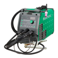
Switch on, press, weld
Lasprogramma instellen
• Zet de machine aan via de hoofdschakelaar (2)
• Kies proces
Raadpleeg de quickguide.
• De lasstroom en de secundaire parameters instellen.
Voor meer informatie wat
betreft het instellen van de
parameters, raadpleeg de
quickguide
• De machine is klaar om te lassen
t 1 t 2
%
V
TIG AC/DC
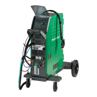
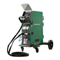
Onderstel met autotrafo-unit voor het automatisch aanpassen
van de aansluitspanning (speciale uitrusting)
Machines die geleverd worden met een autotransformator
kunnen worden aangesloten op de volgende netvoeding:
3*230V, 3*400V, 3*440V en 3*500V.
Door op de schakelaar (18) te drukken, schakelt de
autotransformator in (LED licht groen op). Na 40 minuten van
inactiviteit schakelt de ingebouwde energiebesparende functie
de lasmachine uit. Druk op de knop (17) om de machine weer in
te schakelen (LED licht rood op).
De energiebesparende functie kan door een technicus
permanent worden uitgeschakeld.
19 Pulse
Key activated = traditional pulse.
20 Pulse setting (traditional)
Press the menu key until the LED shines at:
Pulse time: Welding current period.
Pause time: Base current period.
Base current: %of pulse current.
21 Quick pulse
22 Pulse setting (quick pulse)
Press the menu key until the LED shines at:
Pulse frequency: Pause time + pulse time
Base current: %of pulse current.
23 Synergy PLUS™
Key activated = Synergy PLUS™.
Only mean current can be adjusted.
24 TIG-A-Tack + tack welding function
Key activated = TIG-A-Tack + tack welding
function and setting a tack-welding time
at key 27, allowing TIG-A-Tack welding =
almost invisible tacks.
25 Hotstart (MMA)
Start amp is briefly increased in %of the
welding current.
26 Arc Power (MMA)
Current is briefly increased during short
circuits.
27 Spot time
Time between slope up and slope down.
Tack/TIG-A-Tack time when key 24 is active.
28 Current type
Choice of AC or DC welding.
29 AC-t-balance, time-based
Time balance between positive and
negative half-wave is adjusted in %.
30 AC frequency
Setting of +/- frequency of the AC current.
31 AC-electrode preheating
Automatic electrode preheating.
32 AC-l-balance, amperage-based
The cleaning current of the positive half-
wave is adjusted in %in proportion to the
welding current of the negative half-wave.
33 Choice of secondary parameters
Opens parameters 12-18 and 27.
IGC (12+17)
If IGC (Intelligent Gas Control) is installed
(possible in Pi 350/500), the following
functions are available:
• Synergic gas flow relative to the set
current, if liter is set at less than 4 l
(please refer to the instruction manual
for any adjustment)
• Synergic gas post flow (time) relative to
the set current, if time is set at less than
0 second (please refer to the instruction
manual for any adjustment)
Using IGC requires an inlet pressure to the
welding machine of 1.5-6 bar fromthe gas
supply.
GUIDE PI 200 I 250 I 350 I 500
QUICKGUIDE PI
200 I 250 I 350 I 500
UK
WAARSCHUWING
Wanneer de toortsschakelaar wordt
geactiveerd, staat er spanning tussen
lasdraad en elektrode.
Hefinstructies
Het hefpunt moet
gebruikt worden zoals
aangegeven in de
volgende tekening. De
machine mag niet worden
opgetild wanneer er een
gasfles is aangesloten. (zie
tekening).
Til de machine niet op met de
handgreep.
Ga niet op de handgreep staan.
 Loading...