14
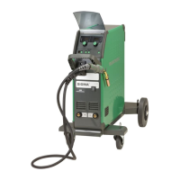
Connection and start-up
Recommended cable dimensions
Welding current DC PULSE
200 A 35 mm² 35 mm²
300 A 50 mm² 70 mm²
400 A 95 mm² / 2x50 mm² 95 mm² / 2x50 mm²
550 A 2x70 mm² 2x70 mm²
Welding process Distance to work piece
(a+b)
Total cable length in
welding circuit (a+b+c)
MIG - pulse 10 m 20 m
MIG - non pulse 30 m 60 m
WARNING
When you activate the torch trigger, there is
voltage applied to the welding wire and electrode.
Warning
Read warning notice and instruction
manual carefully prior to initial
operation and save the information
for later use.
Permissible installation
Mains connection
Connect the machine to the correct mains supply. Please read
the type plate (U
1
) on the rear side of the machine.
Voltage stabilisation kit
The power source is configurable with a voltage stabilisation
kit as a safeguard against larger voltage variations, e.g. in case
of generator use where the machine is connected to a separate
power supply.
Connection of shielding gas
Connect the gas hose, which branches off from the back panel
of the welding machine (3), to a gas supply with pressure
regulator (2-6 bar). (Note: Some types of pressure regulators
require an output pressure of more than 2 bar to function
optimally). One/two gas cylinders can be mounted on the bottle
carrier on the back of the trolley.
Gas consumption
Depending on the welding task, gas type and seam design,
the gas consumption will vary in ranges from 6-7 l/min at low
amperages (<25A) and up to 27 l/min at max. amperage.
Material consumption
Material consumption can be estimated by calculating welding
time in minutes times wire feed speed (m/min) times weight
per meter of the welding consumables in use.
Connection of electrode holder for MMA
The electrode holder and earth cable are connected to
plus connection (10) and minus connection (8). Observe the
instructions from the electrode supplier when selecting polarity.
Important!
In order to avoid destruction of plugs
and cables, good electric contact is
required when connecting earth cables
and welding hoses to the machine.
b
c
a
L1
L2
L3
N
3x400V
yellow/green
brown
black
grey
21
3
Connection of welding hose
4
 Loading...