– 5.6 –
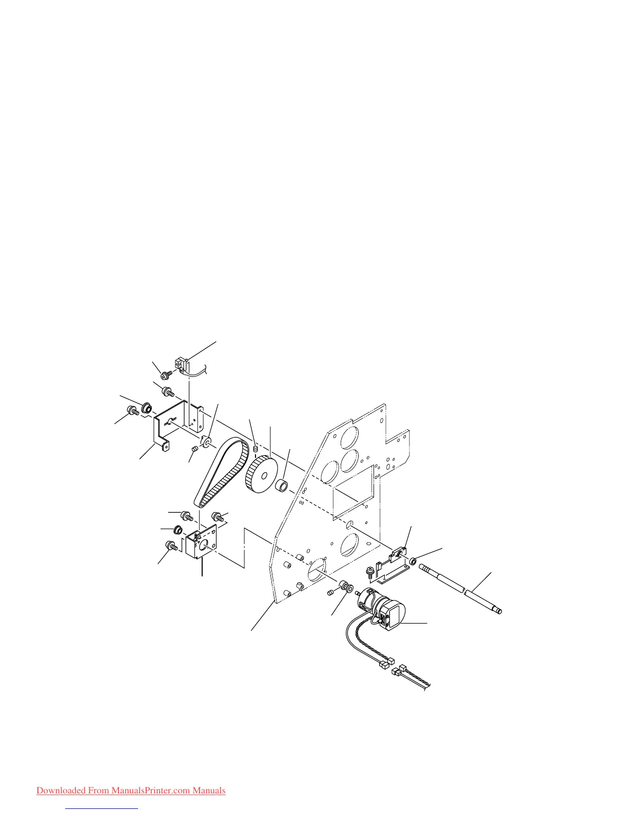
5-1-4. X-motor assy.
[Tools to be used]
• Phillips screwdriver (No.2 for M3 to M5)
[Disassembling procedure]
1) Remove the screw (B3 x 6Ni), then remove the SL cover.
2) Remove the screw (B3 x 6Ni), then remove the YL cover.
3) Remove the left cover.
4) Loosen the screw (P4 x 8SMW) in the X-motor BKT from the left side plate.
5) Remove the screw (P3 x 6SMW) from the X-motor BKT, then remove the X-motor assy.
* Adjust Y-timing belt : Refer to [6-2-5. Adjustment of the X-motor belt tension] P.6-11
[Assembling procedure]
• Assembly is reverse of disassembly.
to Main PCB assy. CN20
to Main PCB assy. CN6,7
B3 x10Bk
P4 x8SMW
P3 x6SMW
P4 x8SMW
P4 x8SMW
P3 x6SMW
SSWP4
XM BKT
Bearing
X-Origin sensor assy.
Pulley stopper
SSWP4
TN15-20 Pulley
Bushing
XM BKT
Bearing
Left side plate
Bearing
Bearing holder 1
X-joing shaft
X-axis motor assy.
TN-15-160 Pulley
SSWP4
Downloaded From ManualsPrinter.com Manuals
 Loading...


